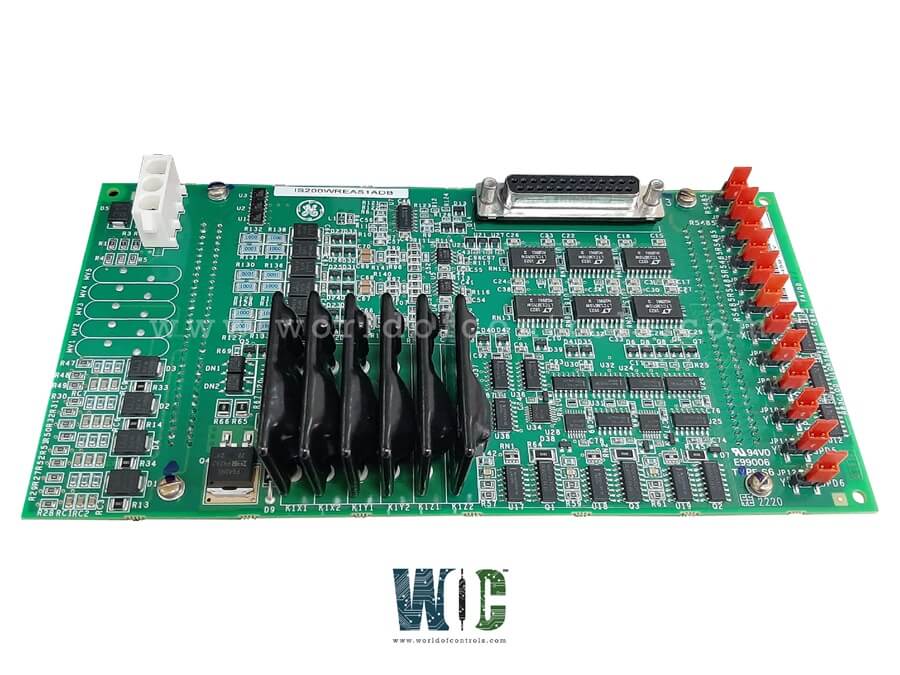
SPECIFICATIONS
Part Number: IS200WREAS1ADB
Manufacturer: General Electric
Series: Mark VIe
Product Type: Aero Turbine Emergency Trip option board
Size: 33.0 cm high x 17.8 cm, wide
Technology: Surface mount
Temperatur:e -30 to 65oC (-22 to +149 oF)
MPU pulse rate range: 2 Hz to 20 kHz
MPU pulse rate accuracy: 0.05% of reading
Contact input voltage: nominal 24 V dc input
Repair: 3-5 days
Availability: In Stock
Country of Manufacturer: United States (USA)
Functional Description
IS200WREAS1ADB is an Aero Turbine Emergency Trip option board developed by General Electric. It is part of the Mark VIe control system. It is designed to enhance the safety and reliability of aero-derivative turbines, this board works in conjunction with TREA terminal boards and is an essential component in turbine trip and emergency shutdown operations. Here’s a breakdown of its functions and key features:
Features
- The board serves as a vital part of the Mark VIe control system, which is known for its robust control capabilities in high-demand environments like those involving GE aero-derivative turbines.
- Working with the PPRA turbine I/O packs, this option board provides crucial emergency trip functionality, enabling the system to monitor and react to abnormal turbine conditions swiftly. The board is designed for use in triple modular redundant (TMR) configurations, improving reliability and ensuring dependable operation under critical conditions.
Key Inputs and Outputs
- Customer Input Terminals: Inputs are accessible through two types of connectors, 24-point pluggable barrier terminal blocks (H1A or S1A). 48-point pluggable Euro-style box terminals (H3A or S3A). These terminals facilitate easy installation and quick connection to various customer inputs.
- Passive Pulse Rate Devices: Six fanned passive pulse rate devices monitor turbine speed by sensing the pulse generated by toothed wheels on the turbine shafts. These devices support up to three shafts, with two sensors per shaft, providing accurate measurements that feed into the emergency trip logic.
- Solid-State Output Contacts: The board includes 24 V dc TMR voted solid-state output contacts for triggering a trip action in emergency situations. Outputs include combinations like TREAH1A, H3A with WREAH1A and TREAS1A, S3A with WREA. These configurations provide a highly reliable, fail-safe method to activate turbine shutdown.
- Voltage Detection Circuits: The board features four voltage detection circuits that monitor trip string voltage within a range of 24-125 V dc. This functionality ensures that the board can accurately detect voltage changes that may indicate unsafe operating conditions.
- Contact Inputs: There are four 24 V dc contact inputs on the WREAS1A portion of the board, which offer additional options for hardware-based or condition-specific trip signals. The inputs are powered via the JH1 connector on the WREA board, ensuring reliable detection of any issues that could require an emergency shutdown.
- Speed Repeater Output: The board provides one speed repeater output for each of the six speed inputs. These outputs, which can utilize either RS-232 or RS-422 transmitters, replicate the pulse rate signals for each monitored shaft, enabling external systems to track turbine speed accurately.
Diagnostics
- Shorted Contact Detection: Feedback from the shorted contact detector is monitored, and if a shorted relay is identified, an alarm is triggered.
- Speed Pickup Fanning Jumpers: Feedback from the speed pickup fanning jumpers is checked. If there's a discrepancy between the expected and actual jumper position, an alarm is raised.
- Speed Repeater Output Monitoring: Each speed repeater output includes a receiver circuit to track output signals. If the output does not match the required speed signal, an alarm is issued to guard against shorted outputs or drive failures in the repeater.
- Composite Diagnostic Alarm (xxDIAG_PPRA): If any of the above signals report an issue, a composite diagnostic alarm, xxDIAG_PPRA, is triggered. These diagnostic alerts can be latched individually and reset with the RESET_DIA command once the signals return to normal.
- Connector ID Verification: Each terminal board connector contains an ID device that is queried by the I/O pack. This device is a read-only chip holding the terminal board’s serial number, type, revision, and location. If the PPRA detects a mismatch, a hardware incompatibility fault is generated.
- Wetting Power Presence: The presence of wetting power is verified to ensure reliable operation.
WOC has the largest stock of Speedtronic control spares. Please contact our staff by phone or email for pricing and availability on any parts and repairs
FREQUENTLY ASKED QUESTIONS
What is IS200WREAS1ADB?
It is an Aero Turbine Emergency Trip option board developed by General Electrics.
What is the function of Jumpers JP1 and JP2 on the terminal board?
Jumpers JP1 and JP2 are used to configure the fanning of the X channel speed inputs to the Y and Z PPRA I/O packs. For proper operation with TREA and WREA configurations, it is necessary that these jumpers are installed.
How do WREA jumpers JP1 through JP12 affect the system?
Jumpers JP1 through JP12 on the WREA board are utilized to set up and control the output behavior of the system, allowing for precise adjustments based on the specific operational requirements of the turbine control setup.
