SPECIFICATIONS
Part No.: IS200VVIBH1CBC
Manufacturer: General Electric
Country of Manufacture: United States of America (USA)
Product Type: Vibration Monitor Board
Availability: In Stock
Series: Mark VI
Functional Description
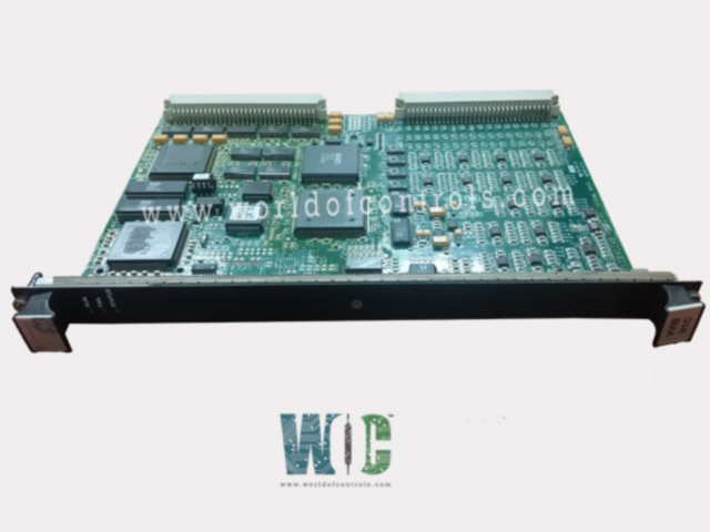
IS200VVIBH1CBC is a Vibration Monitor Board developed by GE. It is part of the Mark VI series. Vibration Monitor board serves as a component processing vibration probe signals obtained from either the TVIB or DVIB terminal board. With the capability to accommodate signals from up to 14 probes directly connected to the terminal board, the VVIB monitors and analyzes vibration levels within the system.
Features
- Probe Compatibility: The board is designed to work seamlessly with Bently Nevada probes, renowned for their reliability and accuracy in shaft vibration monitoring applications.
- Signal Processing: Processes the incoming vibration signals, digitizing them for further analysis and interpretation. This digitization ensures precise and reliable measurement of vibration levels across various components.
- Connection Options: Two boards can be cabled to the processor board, providing flexibility in system configuration and scalability to accommodate varying monitoring requirements.
- Data Transmission: Once digitized, the vibration signals are transmitted over the VME bus to the controller. This transmission enables real-time monitoring and analysis of vibration levels, allowing for timely detection of any abnormal or potentially harmful conditions.
Protective functions
- Vibration Monitoring: Proximity probes are utilized to monitor the peak-to-peak radial displacement of the shaft, specifically the shaft motion within the journal bearing, in two radial directions. Non-contacting probes and Proximitors are employed in this system to detect alarms, trips, and faults associated with abnormal shaft vibrations.
- Rotor Axial Position Monitoring: A probe is installed in a bracket assembly off the thrust bearing casing to observe the motion of the thrust collar on the turbine rotor.
- Non-contacting probes and Proximitors are utilized to detect thrust bearing wear alarms, trips, and faults, ensuring the integrity of the turbine's axial position.
- Differential Expansion Monitoring: This application employs non-contacting probe(s) and Proximitor(s) to detect alarms, trips, and faults caused by excessive expansion differential between the rotor and the turbine casing. By monitoring the expansion differentials, the system can prevent potential damage and ensure safe operation of the turbine.
- Rotor Eccentricity Monitoring: A probe is positioned adjacent to the shaft to continuously sense the surface and update the turbine control system. Eccentricity calculations are performed once per revolution while the turbine is on turning gear, providing alarm and fault indications to address any deviations from the expected eccentricity levels.
Installation
- Power Down the VME Processor Rack: Prior to installation, power down the VME processor rack to prevent any potential electrical hazards and ensure safety during the installation process.
- Slide in the Board: Carefully slide the V-type board into the designated slot within the VME processor rack. Ensure that the board aligns correctly with the slot and that its edge connectors are properly positioned.
- Secure the Board: Once the board is fully inserted into the slot, use your hands to push the top and bottom levers inward. This action will help seat the board's edge connectors securely in place within the rack.
- Tighten Captive Screws: After seating the board, locate the captive screws located at the top and bottom of the front panel. Use appropriate tools to tighten these screws securely, ensuring that the board remains firmly in place within the rack.
The WOC team is always available to help you with your Mark VI requirements. For more information, please contact WOC.
Frequently Asked Questions
What is IS200VVIBH1CBC?
It is a Vibration Monitor Board developed by GE under the Mark VI series.
How should I prepare for installing the V-type board?
Before installing the V-type board, it's essential to power down the VME processor rack to ensure safety and prevent any electrical mishaps during the installation process.
What should I do after sliding in the board?
After sliding the V-type board into the designated slot, make sure to push the top and bottom levers inward with your hands. This action helps to seat the board's edge connectors securely within the rack.
