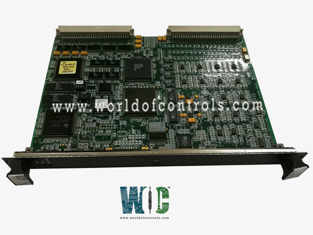
World Of Controls understands the criticality of your requirement and works towards reducing the lead time as much as possible.
IS200VVIBH1CAC - Vibration Monitor Board is available in stock which ships the same day.
IS200VVIBH1CAC - Vibration Monitor Board comes in UNUSED as well as REBUILT condition.
To avail our best deals for IS200VVIBH1CAC - Vibration Monitor Board, contact us and we will get back to you within 24 hours.
Part No.: IS200VVIBH1CAC
Manufacturer: General Electric
Country of Manufacture: United States of America (USA)
Size: 33.0 cm high x 17.8 cm wide
Technology: Surface mount
Temperature Operating: -30 to 65 oC
Number of outputs: Generator breaker coil, 5A at 125 V dc
Power supply voltage: Nominal 125 V dc to breaker coil
MPU pulse rate range: 2 Hz to 20 kHz
MPU pulse rate accuracy: 0.05 percent of reading
Product Type: Vibration Monitor Board
Availability: In Stock
Series: Mark VI
IS200VVIBH1CAC is a Vibration Monitor Board developed by GE. It is a part of Mark VI control system. The Mark VI system incorporates Bently Nevada probes for precise shaft vibration monitoring. This process involves the utilization of the Vibration Monitor Board (VVIB), which is responsible for processing the signals received from the vibration probes connected to the TVIB terminal board.
The WOC team is always available to help you with your Mark VI requirements. For more information, please contact WOC.
What is IS200VVIBH1CAC?
It is a Vibration Monitor Board developed by GE under the Mark VI series.
What is the power source for the probes?
The probes are powered by -24 V dc obtained from the -28 V dc bus. Each probe supply is current-limited to ensure proper operation and prevent overload. The load per transducer is limited to 12 mA.
How is the probe signal sampled?
The Vibration Monitor Board (VVIB) utilizes a 16-bit analog-to-digital converter (A/D converter) with 14-bit resolution for precise signal sampling. In fast scan mode (applicable for RPM ranging from 4,000 to 17,500), the sampling rate is 4,600 samples per second. For RPM less than 4,000, the sampling rate is 2,586 samples per second if nine or more probes are used. All inputs are simultaneously sampled within time windows of 160 ms, ensuring accurate data acquisition.
What are the RPM limitations for utilizing vibration channels?
If the rated RPM exceeds 4,000 rpm, up to eight vibration channels can be used, while the remaining channels may be allocated for proximity or position measurements. However, if the rated RPM is less than 4,000, the system supports the use of all 16 vibration channels in addition to other probe functionalities.
How accurate are the buffered outputs?
The buffered outputs maintain a high level of accuracy, with an amplitude accuracy of 0.1 percent when transmitting signals to the Bently Nevada 3500 vibration analysis system. This ensures precise and reliable vibration data for comprehensive system monitoring and analysis.