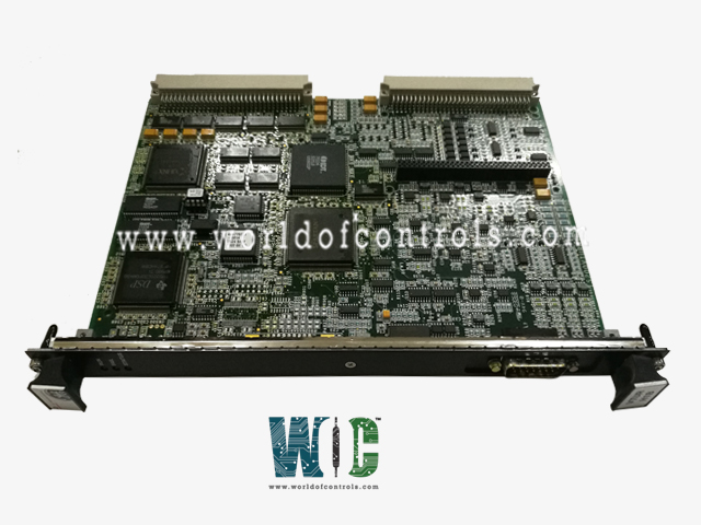
IS200VTURH1BAB - Primary Turbine Protection Board

IS200VTURH1BAB - Primary Turbine Protection Board IS200VTURH1BAB - Primary Turbine Protection Board

World Of Controls understands the criticality of your requirement and works towards reducing the lead time as much as possible.

IS200VTURH1BAB - Primary Turbine Protection Board is available in stock which ships the same day.

IS200VTURH1BAB - Primary Turbine Protection Board comes in UNUSED as well as REBUILT condition.

To avail our best deals for IS200VTURH1BAB - Primary Turbine Protection Board, contact us and we will get back to you within 24 hours.

SPECIFICATIONS

Part No.: IS200VTURH1BAB
Manufacturer: General Electric
Country of Manufacture: United States of America (USA)
MPU pulse rate range: 2 Hz to 20 kHz
MPU pulse rate accuracy: 0.05 percent of reading
MPU input circuit sensitivity: 27 mV pk (detects 2 rpm speed)
Product Type: Primary Turbine Protection Board
Availability: In Stock
Series: Mark VI

Functional Description

IS200VTURH1BAB is a primary turbine protection board developed by GE. It is part of the Mark VI series. The board undertakes a pivotal role in accurately measuring turbine speed through four passive pulse rate devices. This data is then relayed to the controller, which is responsible for generating the primary overspeed trip. This trip acts as a critical safety measure in cases of excessive turbine speed, ensuring system safety.

Generator Synchronization and Main Breaker Control

  • The module plays a critical role in the synchronization of generators and control of the main breaker within turbine systems. Module facilitates automatic synchronization of generators and governs the closure of the main breaker, ensuring efficient and reliable power flow management.
  • Generator synchronization is achieved through advanced algorithms embedded within the module. By synchronizing the rotational speed, phase angle, and voltage of multiple generators, this module enables seamless parallel operation, thereby optimizing power generation efficiency and reliability.
  • Furthermore, the module controls the closure of the main breaker, a crucial function in regulating the flow of electrical power within the turbine system. By precisely coordinating the timing of main breaker closure, the module ensures proper distribution of power and protection against overloads or faults, thereby safeguarding the integrity of the electrical infrastructure.

Monitoring Shaft Voltage and Current

  • Monitoring shaft voltage and current is a critical function performed by the board, contributing significantly to the prevention of potential operational hazards. By continuously monitoring these parameters, the board plays an essential role in promptly detecting irregularities, which is vital for maintaining operational integrity and safety.
  • The importance of monitoring induced shaft voltage and current cannot be overstated, as they serve as key indicators of the health and performance of rotating machinery. Any deviations from expected levels could signify underlying issues such as insulation degradation, bearing damage, or electrical faults. Therefore, real-time monitoring allows for early detection of such anomalies, enabling proactive maintenance and risk mitigation.
  • Utilizing sophisticated sensing and measurement techniques, the board is capable of accurately monitoring shaft voltage and current levels. Any deviations from normal values trigger alarms or alerts, prompting operators or automated systems to investigate further. This proactive approach to monitoring and maintenance helps prevent potential equipment damage, production downtime, or safety hazards.

Supervision of Flame Detectors in Gas Turbine Applications

  • The board is responsible for supervising eight Geiger-Mueller flame detectors within gas turbine applications, each connected to the Turbine Rack Power Supply (TRPG). These detectors draw power from an external supply and play a pivotal role in promptly detecting and responding to flame-related issues, thereby enhancing overall system safety.
  • Flame detectors are vital components within gas turbine systems, tasked with swiftly detecting the presence or absence of flames within the combustion chamber. Their reliable operation is crucial for providing timely feedback to the control system, enabling rapid shutdown procedures or corrective actions in the event of flameout or combustion instability.
  • As the central supervisory unit, the board continuously monitors the status and performance of each flame detector. Any deviations or malfunctions detected by the board trigger alerts or alarms, prompting immediate investigation and corrective measures. This proactive approach ensures that potential issues with the flame detectors are addressed promptly, minimizing risks and maintaining operational integrity.
  • The oversight provided by the board significantly enhances system safety by facilitating swift detection and response to flame-related issues. By ensuring the proper functioning of flame detectors, the board mitigates the risk of uncontrolled combustion events, equipment damage, and safety hazards for personnel.

Control of Primary Overspeed Trip Relays and Emergency Solenoids

  • The module assumes a pivotal role in overseeing and managing critical safety mechanisms, particularly in controlling three primary overspeed trip relays situated on the TRPx terminal board. This function is integral to responding swiftly and effectively to overspeed events, safeguarding both equipment and personnel within the turbine system.
  • The primary overspeed trip relays serve as vital safeguards against turbine overspeed conditions, which pose significant risks to system integrity. Located strategically on the TRPx terminal board, these relays detect and respond to deviations from safe operating speeds. Upon receiving signals indicating an overspeed condition, these relays initiate immediate corrective actions to prevent catastrophic failures or damage to the turbine.
  • VTUR also generates trip signals to activate emergency solenoids in response to overspeed events. These solenoids serve as secondary safety measures, offering redundancy in safety protocols to ensure robust protection against overspeed conditions. Their activation, swiftly engages additional safety mechanisms to mitigate risks associated with overspeed events, thereby enhancing overall system safety and reliability.
  • In enhancing safety redundancy, VTUR provides multiple initiation points for overspeed trip events. Alongside VTUR, the primary overspeed trip relays and emergency solenoids can also be initiated by VPRO, further reinforcing the system's resilience and reliability in safeguarding against overspeed conditions.

Interface with Trip Solenoids and Redundancy Systems

  • It interfaces with TRPx, utilizing nine magnetic relays for interaction with three trip solenoids (ETD).
  • This interface ensures robustness and reliability, employing Triple Modular Redundancy (TMR) systems with nine relays or three relays in simplex systems for trip solenoid control. This redundancy enhances safety in critical turbine operations.

Shaft Current Measurement

  • The shaft current input system is designed to precisely measure the current flowing through the shaft in amperes alternating current (AC). It utilizes a shunt voltage of up to 0.1 volts peak-to-peak to gauge this current accurately. This measurement capability is crucial for monitoring and analyzing the current levels within the shaft, ensuring optimal operation and early detection of potential issues.

Generator and Bus Voltage Sensors

  • Two single-phase potential transformers (PTs) are employed to sense the voltage in both the generator and bus systems.
  • The secondary output of these transformers supplies a nominal 115 volts root mean square (Vrms).
  • Each input, remarkably efficient, has a loading of less than 3 volt-amperes (VA). This setup enables the accurate measurement of voltages in these systems, allowing for precise monitoring and control.

Synchronization and Voltage Range

  • The allowable voltage range for synchronization purposes spans from 75 to 130 Vrms. This range ensures that synchronization processes occur within safe and specified voltage parameters. Additionally, each PT input is equipped with magnetic isolation employing a 1,500 volts root mean square (Vrms) barrier, which effectively prevents interference and ensures system safety.

Cable Length and Wiring Specifications

  • The system allows for a cable length of up to 1,000 feet, utilizing 18 AWG wiring.
  • This generous length allowance and specific wiring gauge facilitate flexibility in system installation while maintaining efficient signal transmission and integrity over considerable distances.

Synchronizing Measurements Precision

  • Precision is a key feature in synchronizing measurements.
  • The system boasts an impressive frequency accuracy of 0.05 percent over a frequency range of 45 to 66 Hertz (Hz). It also monitors the zero crossing of the inputs on the rising slope, ensuring synchronization accuracy.
  • Moreover, its phase difference measurement capability maintains accuracy within better than 1 degree, crucial for precise synchronization processes.

Contact Voltage Sensing and Isolation

  • The system is equipped with contact voltage sensing capabilities.
  • A voltage of 20 volts direct current (VDC) indicates a high status, while 6 VDC indicates a low status.
  • Each circuit is optically isolated and filtered for 4 milliseconds, ensuring reliable and accurate sensing while preventing interference and maintaining system stability. This feature enhances safety and ensures the system's operational reliability in voltage-based signal sensing.

The WOC team is always available to help you with your Mark VI requirements. For more information, please contact WOC.

Frequently Asked Questions

What is IS200VTURH1BAB?
It is a primary turbine protection board developed by GE under the Mark VI series.

What diagnostic checks does VTUR perform?
Feedback discrepancies from solenoid relay drivers and relay contacts. Loss of solenoid power, abnormal flame detector voltage, or specific relay conditions.

How are diagnostic signals managed?
Faulty diagnostic signals can be latched and reset using RESET DIA for resolution.

What's the significance of terminal board connectors and ID devices?
Each connector contains an ID chip storing essential board information. VTUR reads these chips; a mismatch triggers a hardware incompatibility fault.