SPECIFICATIONS
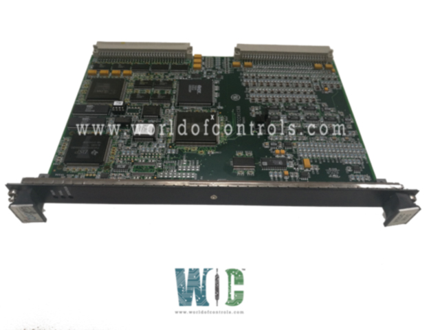
Part No.: IS200VTCCH1CBC
Manufacturer: General Electric
Country of Manufacture: United States of America (USA)
Number of channels :24
Thermocouple types: E, J, K, S, T
Span: -8 mV to +45 mV
Product Type: Thermocouple Processor Board
Availability: In Stock
Series: Mark VI
Functional Description
IS200VTCCH1CBC is a Thermocouple Processor Board developed by GE. It is a part of Mark VI control system. The board is designed to accept inputs from 24 different types of thermocouples, including type E, J, K, S, or T. The thermocouple inputs are wired to two terminal blocks located on the terminal board, known as TBTC. These terminal blocks serve as connection points for the thermocouple cables.
Features
- Communication Interface: Cables equipped with molded plugs facilitate the connection between the terminal board (TBTC) and the VME rack, where the VTCC thermocouple processor board is housed. This ensures seamless communication between the thermocouple inputs and the processing unit.
- Simplex and TMR Control: Depending on the system requirements, the TBTC terminal board offers flexibility in configuration. It can support both simplex (TBTCH1C) and triple modular redundant (TMR) control (TBTCH1B). This allows for tailored integration based on redundancy needs and system architecture.
Installation
- Mounting the Terminal Board: Begin by securely mounting the terminal board in the designated location within the system setup.
- Wiring Thermocouple Inputs: Connect the thermocouple inputs to the terminal blocks on TBTC. Ensure proper labeling and organization to facilitate easy identification and troubleshooting.
- Connecting to VME Rack: Utilize cables with molded plugs to establish connections between the terminal board and the VTCC thermocouple processor board housed in the VME rack.
- Configuration Flexibility: Depending on the specific requirements of the application, configure the terminal board for either simplex or TMR control mode, as needed.
- Testing and Validation: Once installed, conduct thorough testing and validation procedures to ensure proper functionality and communication between the thermocouple inputs and the processing unit.
Fault detection
- High/Low (Hardware) Limit Check: Hardware limit checks are performed regularly to detect any deviations from preset high and low levels. These limits are set to safeguard against extreme conditions that could potentially compromise system integrity or lead to equipment failure. If a measured parameter exceeds or falls below these predetermined limits, a fault signal is triggered, indicating the presence of an abnormal condition that requires attention.
- High/Low System (Software) Limit Check: In addition to hardware-based limit checks, software-based limit checks are implemented within the system. These software limits are defined based on the operational parameters and performance requirements of the system. The software continuously monitors system variables and compares them against the predefined limits. If any parameter surpasses the high or low thresholds set by the software, it triggers a fault condition, prompting appropriate corrective action.
- Monitoring Readings from all TCs, CJs, Calibration Voltages, and Calibration Zero Readings: Comprehensive monitoring extends to all components critical for system operation, including thermocouples (TCs), cold junctions (CJs), calibration voltages, and calibration zero readings. Regular monitoring of these components ensures that they are functioning within acceptable tolerances and accurately reflecting the system's operational conditions. Any deviations or discrepancies detected during monitoring are promptly flagged as potential faults or anomalies, prompting further investigation and corrective measures.
The WOC team is always available to help you with your Mark VI requirements. For more information, please contact WOC.
Frequently Asked Questions
What is IS200VTCCH1CBC?
It is a thermocouple processor board developed by GE under the Mark VI series.
What is the cold junction temperature accuracy?
The cold junction temperature accuracy is 2oF, ensuring precise measurement and control of temperature within the system.
What is the maximum conformity error for cold junction temperature?
The maximum conformity error, representing the software error, is limited to 0.25oF, ensuring reliable and accurate temperature readings.
What is the measurement accuracy excluding the cold junction reading?
The measurement accuracy, excluding the cold junction reading, is 53 mV, providing high precision in temperature measurement.
