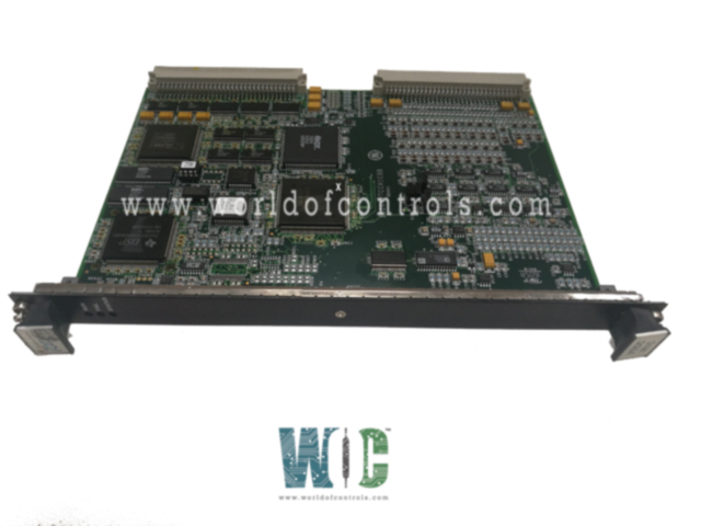
World Of Controls understands the criticality of your requirement and works towards reducing the lead time as much as possible.
IS200VTCCH1CBA - Thermocouple Processor Board is available in stock which ships the same day.
IS200VTCCH1CBA - Thermocouple Processor Board comes in UNUSED as well as REBUILT condition.
To avail our best deals for IS200VTCCH1CBA - Thermocouple Processor Board, contact us and we will get back to you within 24 hours.
SPECIFICATIONS:
Part Number: IS200VTCCH1CBA
Manufacturer: General Electric
Series: Mark VI
Function: Thermocouple Processor Board
Number of Channels: 12
Thermocouple Types: E, J, K, S
Span: -8 mV to +45 mV
A/D Converter: 16-bit
Common Mode Voltage: +5 Volts
Normal Mode Rejection: 250 mV
Microprocessor: AMD-K6 300 MHz
Operating temperature: -30 to 65 °C
Size: 8.26 cm wide x 4.19 cm
Technology: Surface Mount
Repair: 3-7 days
Availability: In Stock
Country of Origin: United States
FUNCTIONAL DESCRIPTION:
IS200VTCCH1CBA is a Thermocouple Processor Board manufactured and designed by General Electric as part of the Mark VI Series used in GE Speedtronic Control Systems. The Thermocouple Input (VTCC) board is designed to accept 24 thermocouple inputs, which are wired through either the TBTC or DTTC terminal boards. These boards connect to the VTCC processor board, located in the VME rack, using cables with molded plugs. The TBTC terminal board supports both simplex (TBTCH1C) and triple module redundant (TMR) control (TBTCH1B) configurations, ensuring flexibility in system architecture.
The VTCC is available in two variants optimized for different applications. The VTCCH1 version is tailored for gas turbine control and supports thermocouple types E, J, K, S, and T, along with millivolt (mV) inputs within a span of -8 mV to +45 mV. The VTCCH2 version, suited for general-purpose applications, supports the same types as VTCCH1, plus additional thermocouple types B, N, and R, with an extended mV input span of -20 mV to +95 mV. Both VTCC versions are compatible with the same TBTC terminal boards, offering consistent connectivity and simplified system integration.
INSTALLATION:
Power down the VME processor rack before beginning the installation, ensure that all power to the VME processor rack is turned off. This is a critical safety measure to prevent electrical shock, damage to the board, or disruption to other components in the system. Verify that all indicator lights are off and that there is no residual voltage present before proceeding.
Slide the VTCC board in and push the top and bottom levers in with your hands to seat its edge connectors. Carefully align the VTCC board with the guide rails of the designated slot in the VME rack. Gently slide the board into the slot until you feel resistance from the backplane connectors. At this point, use your hands to press the top and bottom levers inward to fully seat the board’s edge connectors into the VME backplane. This action ensures a firm and secure electrical connection between the board and the system bus. Do not use tools to push the levers, as this may cause physical damage to the board or connectors.
Tighten the captive screws at the top and bottom of the front panel. Once the board is properly seated, locate the captive screws at both the top and bottom of the VTCC board’s front panel. Use a screwdriver to gently tighten these screws, securing the board in place. This helps prevent loosening due to vibration or thermal cycling during operation, ensuring long-term stability and connectivity within the control system.
OPERATION:
The VTCC board supports a wide range of thermocouple types depending on the model. The VTCCH1 variant is compatible with Type E, J, K, S, and T thermocouples, while the VTCCH2 version extends support to include Types B, N, and R in addition to those supported by VTCCH1. Both grounded and ungrounded thermocouples can be used. These sensors can be installed at distances of up to 300 meters (984 feet) from the turbine control cabinet, provided the total two-way cable resistance does not exceed 450 ohms.
To ensure signal integrity, the system incorporates high-frequency noise suppression and includes two cold junction (CJ) reference devices mounted directly on the terminal board. The VTCC board performs software-based linearization for each thermocouple type to deliver accurate temperature readings. If a thermocouple input exceeds predefined hardware limits, it is automatically excluded from the scanning sequence to protect the accuracy and stability of other channels.
WOC has the largest stock of Replacement parts for GE Speedtronic Turbine Control Systems. We can also repair your faulty boards and supply unused and rebuilt boards backed up with a warranty. Our team of experts is available around the clock to support your OEM needs. Our team of experts at WOC is happy to assist you with any of your automation requirements. For pricing and availability on any parts and repairs, kindly contact our team by phone or email.
What is the primary function of the VTCC board?
The VTCC board, also known as the Thermocouple Processor Board, is designed to receive and process temperature signals from thermocouples. It converts these inputs into accurate and usable temperature data for turbine control systems, helping maintain optimal operational performance and safety in both gas turbine and general industrial applications.
Which thermocouple types are supported?
The VTCC board supports a variety of thermocouple types depending on the variant. The VTCCH1 model is compatible with thermocouple types E, J, K, S, and T. The VTCCH2 version includes support for those types as well as B, N, and R. In addition to thermocouples, both models also accept direct millivolt (mV) inputs, making them versatile for various temperature measurement needs.
How does the VTCC board perform linearization of thermocouple signals?
The VTCC board performs linearization through software algorithms that are specific to each thermocouple type. Since thermocouple outputs are inherently nonlinear, this software-based approach converts raw voltage signals into accurate temperature values.