World Of Controls understands the criticality of your requirement and works towards reducing the lead time as much as possible.
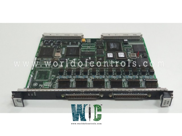
IS200VSCAH2AAB - Serial Communication I/O Board is available in stock which ships the same day.
IS200VSCAH2AAB - Serial Communication I/O Board comes in UNUSED as well as REBUILT condition.
To avail our best deals for IS200VSCAH2AAB - Serial Communication I/O Board, contact us and we will get back to you within 24 hours.
Part No.: IS200VSCAH2AAB
Manufacturer: General Electric
Country of Manufacture: United States of America (USA)
Number of Serial Ports: 6 per board
Size: 10.25 in. x 0.78 x 7.375 in
Product Type: Serial Communication Input/Output Board
Availability: In Stock
Series: Mark VI
IS200VSCAH2AAB is a Serial Communication Input/Output Board developed by GE. It is a part of the Mark VI control system. The Serial Communications Board serves as a vital component in the system's communication infrastructure, enabling interactions with external devices through various serial communication protocols such as RS-232C, RS422, and RS485. The DSCB, mounted on a DIN rail, acts as the interface between the VSCA and external devices. The wiring between the VSCA and DSCB is facilitated through the J6 and J7 front panel connectors, each utilizing a 37-pin D shell connector with group shielded twisted pair wiring.
Step 1: Power Down the VME I/O Processor Rack
Before handling the board, ensure that the VME I/O processor rack is completely powered down. This step is essential for safety and to prevent electrical damage to the board or the rack. Confirm that all power sources are disconnected, and allow the system to discharge any residual power.
Step 2: Insert the Board into the Rack
Gently slide the V-type board into the designated slot within the VME rack. Align the board's edge connectors with the corresponding slots on the rack. Once aligned, use your hands to push the top and bottom levers simultaneously to ensure the edge connectors are fully seated. This ensures proper electrical contact and mechanical stability.
Step 3: Secure the Board
Once the board is in place, locate the captive screws at the top and bottom of the board's front panel. Tighten these screws securely to hold the board in place and prevent it from shifting during operation. Proper fastening helps maintain consistent connections and reduces the risk of vibration-related issues.
Step 4: Connect the Cables
The terminal boards are connected via the J6 and J7 connectors located on the front panel of the V-type board. Use the provided latching type connectors to attach the cables securely. Ensure the connectors are fully latched to avoid accidental disconnection during operation.
Step 5: Power Up and Check Diagnostics
After installing the board and connecting the cables, power up the VME rack. Observe the diagnostic lights located at the top of the board’s front panel. These indicators provide critical information about the board's status and functionality. For detailed diagnostic information, refer to the relevant section in the documentation provided with the board.
The WOC team is always available to help you with your Mark VI requirements. For more information, please contact WOC.
What is IS200VSCAH2AAB?
It is a serial communication input/output board developed by GE under the Mark VI series.
How does the board handle communication issues on its ports?
The board monitors each port for communication problems. If it detects issues such as no response, bad data, or a non-functional port, it sets a diagnostic fault. This fault, known as L3DIAG VSCA, covers the entire board and can be individually latched and reset using the RESET DIA signal.
What information is stored in the ID device of terminal and I/O boards?
Each terminal and I/O board has its own ID device containing crucial details such as the serial number, board type, revision number, and JA1 connector information. Mismatch during interrogation triggers a hardware incompatibility fault.
How are diagnostic signals managed in the system?
Diagnostic signals, including communication faults and hardware incompatibility, can be individually latched for detailed analysis. These signals are reset using the RESET DIA signal once the issues are addressed.
What happens when there is a hardware incompatibility in the ID interrogation process?
In case of a hardware incompatibility due to a mismatch during ID interrogation, a fault is created. This fault promptly alerts the system to address any inconsistencies in hardware configuration, ensuring optimal performance.