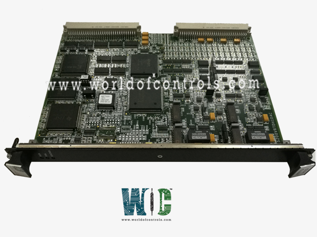
SPECIFICATIONS
Part No.: IS200VRTDH1DAB
Manufacturer: General Electric
Country of Manufacture: United States of America (USA)
Number of channels: 16 channels
Span: 0.3532 to 4.054 V
Common mode voltage range: 5 V
Maximum lead resistance: 15 ohm maximum
Fast scan: 40 ms (25 Hz)
Power consumption: Less than 12 W
Product Type: Resistance Temperature Device
Availability: In Stock
Series: Mark VI
Functional Description
IS200VRTDH1DAB is a resistance temperature device developed by GE. It is a part of the Mark VI control system. The RTD processor board (VRTD) and its associated terminal boards form an integrated system for accurate temperature sensing and monitoring. The precise wiring, use of specialized cables, and collaborative processing ensure reliable temperature data collection and transmission within the broader control system.
Signal Excitation and Processing
- Excitation by VRTD: The processor board is responsible for exciting the RTDs. This excitation process ensures that the RTDs produce accurate and reliable signals corresponding to the temperature conditions they are monitoring.
- Signal Return and Processing: The signals generated by the RTDs in response to the excitation are then returned to the VRTD processor board. The VRTD processes these signals, extracting temperature information for further analysis and transmission.
Digital Temperature Values and Data Transfer
- I/O Processor Board Conversion: In collaboration with the I/O processor board, converts the analog signals from the RTDs into digital temperature values. This conversion process enhances the precision and compatibility of the temperature data for subsequent stages.
- VME Backplane Communication: The digital temperature values are transmitted over the VME backplane, a high-speed communication channel within the system. This data transfer is a critical step in relaying temperature information to the VCMI board.
- Controller Integration: Finally, the board forwards the digital temperature values to the controller, allowing the system to make informed decisions based on the monitored temperature conditions. This integration contributes to the overall control and management of the system.
Operation
- High-Frequency Decoupling for Signals: One of the critical features of the Resistance Temperature Device (RTD) processing system is the implementation of high-frequency decoupling for RTD signals at the point of signal entry. This design element serves to safeguard the integrity of RTD signals by effectively mitigating the impact of high-frequency noise. As the RTD signals traverse the system, this decoupling to ground ensures that the temperature readings derived from the RTDs are accurate and reliable, even in the presence of potential electromagnetic interference.
- Redundant Pacemakers in Multiplexing: To enhance system robustness and fault tolerance, the RTD multiplexing process on the VRTD boards is orchestrated by redundant pacemakers. This redundancy is crucial in preventing the loss of RTD signals in the control database due to potential failures. Whether it's the loss of a single cable or the failure of a single VRTD board, the redundant pacemakers synchronize the multiplexing operation, ensuring that the control system continues to receive accurate temperature data without interruption.
- Simultaneous RTD Reading and Skewing Mechanism: The boards in different modules, denoted as R, S, and T, are designed to read RTDs simultaneously. However, a strategic skewing mechanism is employed to introduce a temporal offset in the readings. Specifically, the readings are skewed by two. For instance, when module R is actively reading RTD3, module S is reading RTD5, and module T is reading RTD7, and this pattern continues. This deliberate skewing ensures that no two VRTD boards simultaneously excite the same RTD, preventing any potential conflicts and inaccurate readings.
- Preventing Simultaneous Excitation for Data Integrity: The primary goal of the skewing mechanism is to ensure that the same RTD is not excited by two VRTD boards simultaneously. Simultaneous excitation could lead to conflicting signals, resulting in inaccurate temperature readings. By coordinating the readings such that each module is slightly offset from the others, the system guarantees that each board is excited independently during its dedicated reading time. This meticulous approach contributes to data integrity, preventing the production of misleading or erroneous temperature measurements.
The WOC team is always available to help you with your Mark VI requirements. For more information, please contact WOC.
Frequently Asked Questions
What is IS200VRTDH1DAB?
It is a resistance temperature device developed by GE under the Mark VI series.
How many channels does each board support?
Each resistance temperature device board is designed to support a total of 16 channels. This allows the system to concurrently process and monitor temperature data from 16 different sensors, or resistance temperature devices (RTDs).
What is the span of voltage output for the supported RTDs?
The voltage output span for the supported ranges from 0.3532 to 4.054 V. This span represents the range of voltage values corresponding to the temperature variations measured by the RTDs.
What is the resolution of the analog-to-digital (A/D) converter on the boards?
The analog-to-digital (A/D) converter integrated into the boards boasts a resolution of 14 bits. This high-resolution conversion ensures precise and accurate representation of the analog temperature signals into digital values for further processing.
How much power does each board consume?
The power consumption of each board is specified to be less than 12 W. This indicates that the boards are designed to operate efficiently while maintaining a relatively low power draw, contributing to energy efficiency and system stability.
