SPECIFICATIONS
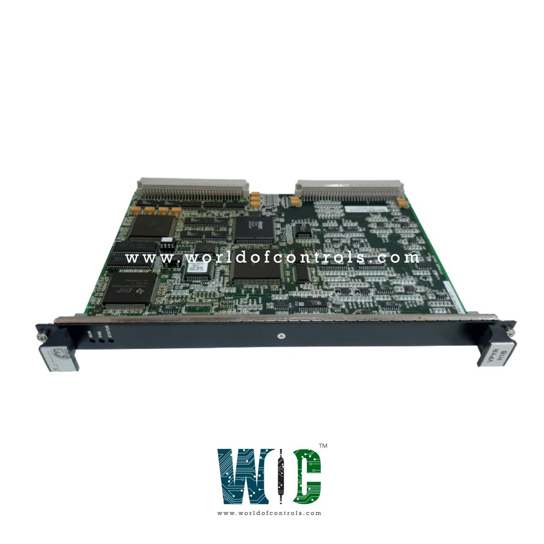
Part No.: IS200VPYRH1BCA
Manufacturer: General Electric
Country of Manufacture: United States of America (USA)
Size 26.04 cm high x 1.99 cm, wide x 18.73 cm, deep
Maximum lead resistance: 15 ohm
Keyphasor probes: 2
Current inputs from pyrometers: 4-20 mA
Keyphasor inputs voltage: 0.5 - 20 V dc
Product Type: Pyrometer Input Board
Availability: In Stock
Series: Mark VI
Functional Description
IS200VPYRH1BCA is a Pyrometer Input Board developed by GE. It is a part of Mark VI control system. The Pyrometer Input (VPYR) board serves as a component within the system, providing essential functionality for monitoring turbine blade temperatures and detecting potential trip conditions. The board enables the dynamic profiling of temperature conditions across rotating turbine blades. It continuously monitors temperature variations to ensure optimal operating conditions and detect any anomalies that could lead to system trips or failures.
Features
- Infrared Turbine Blade Temperature Measurement: The board interfaces with two Infrared Turbine Blade Temperature Measurement System (TBTMS) thermometers, commonly referred to as pyrometers. These pyrometers provide accurate temperature measurements of the turbine blades, allowing for precise monitoring and analysis of temperature profiles.
- Shaft Reference Monitoring: In addition to temperature measurement, the board also interfaces with two Keyphasor Proximitor probes for shaft reference monitoring. This functionality ensures precise synchronization and alignment of the turbine shaft, enhancing overall system reliability and performance.
- Analog-to-Digital Conversion: Dedicated analog-to-digital converters (ADCs) integrated into the VPYR board facilitate high-speed sampling of temperature data. Sampling rates of up to 200,000 samples per second are supported, enabling the capture of burst data for detailed analysis and real-time monitoring.
- Data Availability and Evaluation: Provides fast temperature data that is readily available for display on monitoring interfaces. Additionally, the captured data can be stored for offline evaluation and analysis, allowing for comprehensive assessment of temperature conditions and system performance.
Installation
- Power Down the VME Processor Rack: Before proceeding with the installation, ensure that the VME processor rack is powered down to prevent any electrical hazards or damage to the components.
- Slide in the Board: Carefully slide the board into the designated slot within the VME processor rack. Use both hands to guide the board into place, ensuring that it aligns properly with the edge connectors within the rack.
- Secure the Board: Once the board is properly seated, push the top and bottom levers inward with your hands to secure the board in place. Ensure that the levers engage securely with the rack to prevent any movement or dislodging of the board during operation.
- Tighten Captive Screws: Locate the captive screws located at the top and bottom of the front panel. Use a suitable screwdriver to tighten these screws, ensuring that the board is firmly held in place. The screws serve to enhance the front ground integrity of the board and should be tightened adequately without over-tightening.
Operation
- Analog Signal Processing: Analog signals originating from the TPYR terminal board are transmitted to the processor board. Upon arrival, these signals undergo signal sampling and analog-to-digital conversion, enabling the board to process them digitally for analysis.
- Temperature Profile Calculation: Utilizes the sampled signals to compute temperature profiles across the turbine blades. By analyzing the temperature data from both pyrometer signals, the board generates accurate profiles that reflect the thermal conditions within the turbine.
- Turbine Protection Algorithms: In addition to temperature profile calculation, the board executes specialized turbine protection algorithms. These algorithms are designed to detect abnormal temperature conditions or other factors that could potentially lead to turbine damage or failure.
- Trip Signal Generation: If the protection algorithms identify a critical condition warranting intervention, such as an impending trip scenario, the board generates a trip signal. This trip signal serves as an indication to the control system to initiate protective measures, such as shutting down the turbine or activating safety protocols.
- Signal Validation: Before issuing a trip signal, the board validates the signals and confirms the severity of the detected condition. This validation process ensures that the trip signal is only triggered in response to genuine threats, minimizing the risk of unnecessary shutdowns or disruptions.
The WOC team is always available to help you with your Mark VI requirements. For more information, please contact WOC.
Frequently Asked Questions
What is IS200VPYRH1BCA?
It is a Pyrometer Input Board developed by GE under the Mark VI series.
What is the purpose of the Pyrometer Viewer?
The Pyrometer Viewer serves the function of uploading data captured by the Data Historian.
How does the Pyrometer Viewer differ from the toolbox?
Unlike the toolbox, which is primarily used for system monitoring and control, the Pyrometer Viewer is a separate application dedicated to managing and analyzing data specifically captured by the Data Historian.
Where is the Pyrometer Viewer typically installed?
The Pyrometer Viewer application is commonly loaded onto the HMI (Human-Machine Interface) computer or even onto the field engineer's computer, providing convenient access to the captured data for analysis and evaluation.
What role does the Pyrometer Viewer play in data analysis?
The Pyrometer Viewer facilitates the analysis of pyrometer data, allowing users to visualize and interpret temperature profiles, trends, and other relevant information captured by the Data Historian.
