SPECIFICATIONS
Part No.: IS200VPWRH1AGC
Manufacturer: General Electric
Country of Manufacture: United States of America (USA)
Size: 26.04 cm high x 1.99 cm wide x 18.73 cm deep
Temperature: 0 to 60 oC
Max response time on: 25 ms
Max response time off: 25 ms
Relay contact material: Silver cad-oxide
Number of channels: 48
Product Type: Daughterboard/Sub-assembly
Availability: In Stock
Series: Mark VI
Functional Description
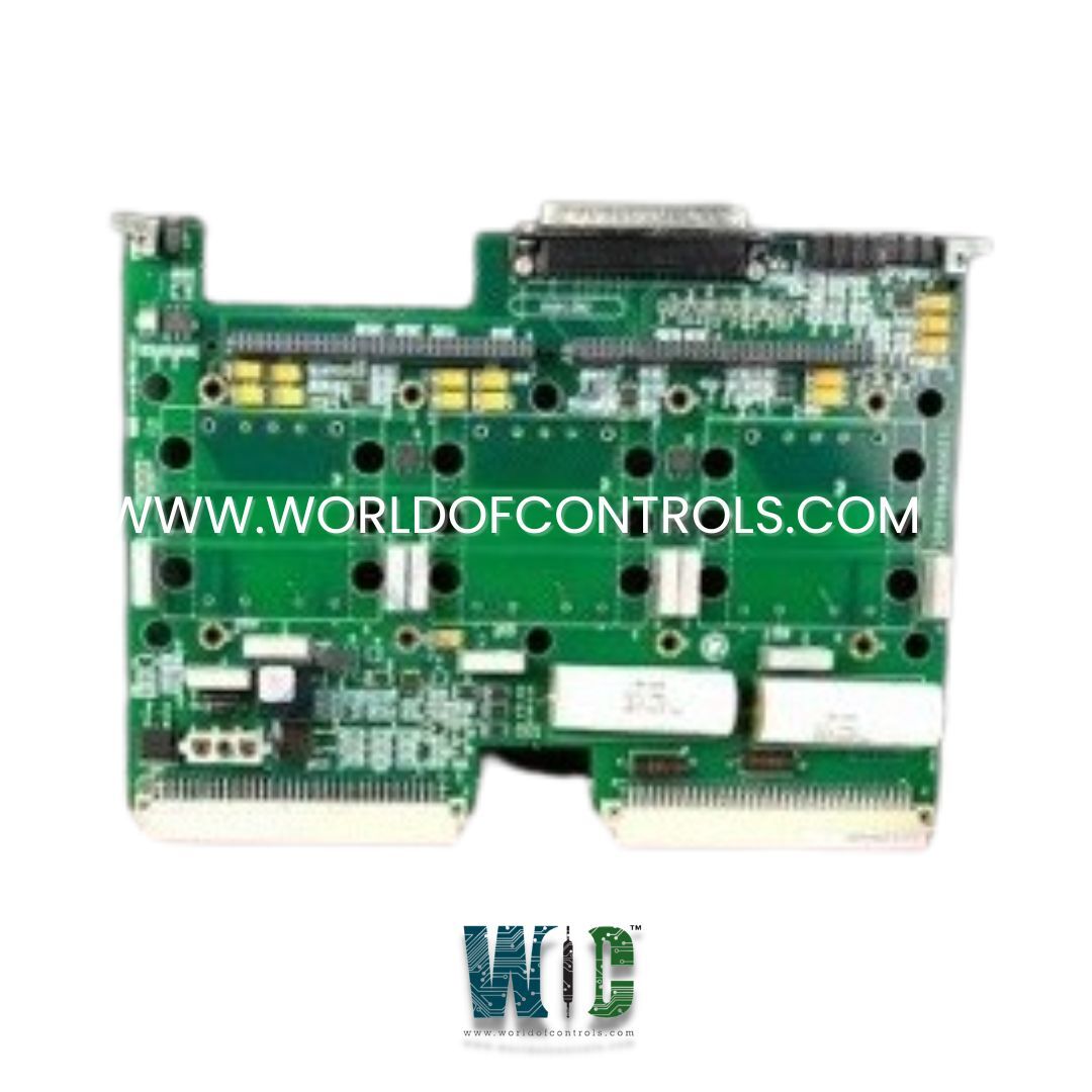
IS200VPWRH1AGC is a Daughterboard/Sub-assembly developed by GE. It is a part of Mark VI control system. It is a component designed to function as a daughterboard or sub-assembly within the VPRO board assembly The Mark VI control system is a versatile and robust solution designed for turbine control and automation. It offers flexibility in configuration and superior reliability in its operations.
Product Attributes
- Mounting Mechanism: It is securely attached to the rest of the assembly using four screws. These screws are threaded through factory-drilled holes and standoffs, ensuring stable and reliable mechanical integration.
- Front Faceplate Connections: Connected at three distinct points to the front faceplate, providing essential interfacing capabilities for the assembly.
- 3-Position Female Plug: Located towards the back of the board, this plug is crucial for power connections. It wires into a corresponding 3-position power plug mounted on the front faceplate. The wiring process is handled on the surface of the board, facilitating efficient power distribution.
- Cable Connector: Situated on the front edge of the board, this connector mounts into the front panel, allowing for streamlined cable management and easy accessibility.
- 64-Position Female Plugs: The board features two 64-position female plugs. These connectors are likely used for high-density signal connections, supporting the communication needs of the assembly.
- Backplane Connector: It does not include any backplane connector. This design choice indicates that the board relies entirely on its other connectors for interfacing with the rest of the system, which may affect how it integrates with other components within the assembly.
System Features
- Simplex Control: The Mark VI system can be configured as a simplex control system, which includes a single controller managing the turbine operations. This configuration is suitable for applications where cost efficiency and simplicity are priorities.
- Triple Modular Redundant (TMR) Control: For enhanced reliability and fault tolerance, the Mark VI system can be configured as a Triple Modular Redundant (TMR) control system. TMR involves three independent control channels, each capable of managing the turbine operations. This redundancy ensures continuous operation even if one or two channels fail, making it ideal for critical applications where uptime and reliability are paramount.
- Single or Multiple Racks: The Mark VI system can be deployed using either a single rack or multiple racks, depending on the complexity and scale of the application. Single rack configurations are suitable for smaller or less complex systems, while multiple rack configurations can accommodate larger, more complex control systems with extensive I/O requirements.
- Local I/O: The system supports local I/O configurations where the input/output modules are located in close proximity to the control hardware. This setup minimizes latency and simplifies wiring.
- Remote I/O: For applications where sensors and actuators are distributed over a wide area, the Mark VI system supports remote I/O configurations. Remote I/O modules communicate with the main control system over a network, providing flexibility in system design and deployment.
- Direct Interface to Sensors and Actuators: The I/O interface of the Mark VI system is designed to connect directly to the sensors and actuators on the turbine. This direct connection eliminates the need for interposing instrumentation, which can introduce additional points of failure and complexity.
- Reliability and Maintenance Benefits: By avoiding the use of interposing instrumentation, the Mark VI system reduces potential reliability issues and simplifies maintenance. Interposing instruments often require regular calibration and maintenance, and their elimination improves overall system reliability and reduces long-term maintenance costs.
The WOC team is always available to help you with your Mark VI requirements. For more information, please contact WOC.
Frequently Asked Questions
What is IS200VPWRH1AGC?
It is a Daughterboard/Sub-assembly developed by GE under the Mark VI series.
What are the VME rack size options for the integrated control and I/O module?
The integrated control and I/O module can be housed in either a 21-slot VME rack, which is suitable for larger systems with more extensive control and I/O needs, or a 13-slot VME rack, which is suitable for smaller systems and can accommodate all necessary boards for controlling a small turbine.
What is the purpose of the backplane connectors in the VME rack?
The backplane of the VME rack has P1 and P2 connectors. The P1 connectors are used for communicating data across the backplane, facilitating data exchange between different VME boards. The P2 connectors handle data communication between the VME boards and the DC-37 pin J3 and J4 connectors located directly beneath each board.
What roles do the J3 and J4 connectors play in the system?
The J3 and J4 connectors are crucial for the system�s data communication. These DC-37 pin connectors are situated beneath each VME board and are used to connect the boards to terminal boards via cables, enabling the transfer of data between the control boards and the external terminal boards that interface with sensors and actuators.
