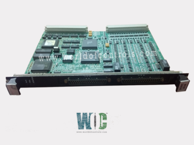
World Of Controls understands the criticality of your requirement and works towards reducing the lead time as much as possible.
IS200VCRCH1BBC - Discrete Input/Output Board is available in stock which ships the same day.
IS200VCRCH1BBC - Discrete Input/Output Board comes in UNUSED as well as REBUILT condition.
To avail our best deals for IS200VCRCH1BBC - Discrete Input/Output Board, contact us and we will get back to you within 24 hours.
Part No.: IS200VCRCH1BBC
Manufacturer: General Electric
Country of Manufacture: United States of America (USA)
Max response time on: 25 ms
Max response time off: 25 ms
Relay contact material: Silver cad-oxide
Size: 10.25 in x 0.782 in x 7.375 in
Temperature: -30 to 65oC
Product Type: Discrete Input/Output Board
Availability: In Stock
Series: Mark VI
IS200VCRCH1BBC is a discrete input/output board developed by GE. It is a part of Mark VI control system. The Discrete Input/Output board, along with its associated daughterboard, facilitates the management of 48 discrete inputs and the control of 24 relay outputs, distributed across four terminal boards. This board is designed to fit into a narrower, single-slot configuration and is installed within the VME I/O rack. The rack is equipped with two sets of J3/J4 plugs to accommodate cables connecting to the TBCI (Contact Input with Group Isolation) and TRLY (Trip Relay) terminal boards.
The WOC team is always available to help you with your Mark VI requirements. For more information, please contact WOC.
What is IS200VCRCH1BBC?
It is a discrete input/output board developed by GE under the Mark VI series.
What do the LEDs on the I/O board front panel indicate?
The normal RUN condition is indicated by a flashing green LED, while FAIL is represented by a solid red LED. The third LED, labeled STATUS, remains off under normal conditions but turns steady orange if a diagnostic alarm condition exists on the board.
How does the diagnostic monitoring work on the I/O board?
The diagnostics on the I/O board monitor each output by sampling and digitizing various parameters such as voltage drops across current sense resistors, D/A outputs, and shutdown relay contacts. Standard diagnostic information includes high and low limit checks, as well as configurable high and low system limit checks. If any output becomes unhealthy, a composite diagnostic alarm occurs.
Can diagnostic signals be individually managed?
Yes, diagnostic signals can be individually latched and then reset with the RESET DIA signal if they return to a healthy state.
What information does the ID device on each cable connector provide?
Each cable connector on the terminal board has its own ID device, which contains information such as the terminal board serial number, board type, revision number, and the JR, JS, and JT connector location. If a mismatch is detected when the ID chip is read by the I/O processor, a hardware incompatibility fault is created.