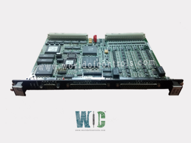
IS200VCRCH1AAA - Discrete Input/Output Board

IS200VCRCH1AAA - Discrete Input/Output Board IS200VCRCH1AAA - Discrete Input/Output Board

World Of Controls understands the criticality of your requirement and works towards reducing the lead time as much as possible.

IS200VCRCH1AAA - Discrete Input/Output Board is available in stock which ships the same day.

IS200VCRCH1AAA - Discrete Input/Output Board comes in UNUSED as well as REBUILT condition.

To avail our best deals for IS200VCRCH1AAA - Discrete Input/Output Board, contact us and we will get back to you within 24 hours.

SPECIFICATIONS

Part No.: IS200VCRCH1AAA
Manufacturer: General Electric
Country of Manufacture: United States of America (USA)
Size: 26.04 cm high x 1.99 cm wide x 18.73 cm deep
Temperature: 0 to 60oC
Max response time on: 25 ms
Max response time off: 25 ms
Relay contact material: Silver cad-oxide
Product Type: Discrete Input/Output Board
Availability: In Stock
Series: Mark VI

Functional Description

IS200VCRCH1AAA is a discrete input/output board developed by GE. It is a part of Mark VI control system. The Contact Input/Relay Output Board in collaboration with its associated daughterboard, is a pivotal component designed to manage 48 discrete inputs and control 24 relay outputs across industrial applications. This versatile board interfaces with four terminal boards, providing structured connectivity for efficient signal processing. With advanced control logic, system monitoring, and diagnostic features, the VCCC seamlessly integrates into larger system architectures, ensuring reliability, scalability, and user-friendly operation.

Features

  • Front-Facing Contact Input Cables: The system's design incorporates a user-friendly approach with contact input cables that conveniently plug into the front of the board. This front-facing accessibility ensures ease of installation, maintenance, and quick identification of connectors, streamlining the overall user experience.
  • Board Overview: The heart of the contact input and relay output management lies in the Contact Input/Relay Output Board. This double-width module is engineered to interface with the VME I/O rack and plays a pivotal role in processing and controlling a significant number of discrete inputs and relay outputs.
  • Discrete Input and Relay Output Capacity: Along with its associated daughterboard, is equipped to handle a substantial workload, accepting up to 48 discrete inputs and effectively controlling 24 relay outputs. This high capacity is particularly advantageous in scenarios where a multitude of input signals need to be processed, and simultaneous control of relay outputs is essential for operational control.
  • Terminal Board Connectivity: Interfaces with the broader system through a total of four terminal boards – two each for the Contact Input (TBCI) and Relay Output (TRLY). These terminal boards provide the physical connection points for the various input and output signals, facilitating a structured and organized cabling setup.
  • Integration in VME I/O Rack: Designed as a double-width module, the module seamlessly integrates into the VME I/O rack. This integration ensures optimal use of space while providing a standardized form factor compatible with the VME architecture. The rack itself features two sets of J3/J4 plugs specifically designated for cables connecting to the TBCI and TRLY terminal boards.
  • Versatility in Configuration: Boards underscores the system's adaptability. Users have the flexibility to choose the most suitable board based on the application's specific needs, allowing for a versatile and customizable configuration within the VME I/O rack.

Installation

  • Power Down the VME I/O Processor Rack: Before initiating the installation process, it is crucial to power down the entire VME I/O processor rack. This ensures a safe environment for handling the hardware and prevents any potential electrical hazards during the installation procedure.
  • Slide in the Board and Engage Levers: With the VME I/O processor rack powered down, carefully slide the board into the designated slot. Use your hands to push the top and bottom levers on the board. This action helps seat the edge connectors securely into the corresponding slots within the rack. Ensuring proper alignment is essential for establishing reliable connections.
  • Tighten Captive Screws on the Front Panel: Once the board is correctly inserted and the levers engaged, proceed to tighten the captive screws located at the top and bottom of the front panel. Captive screws are designed to stay attached to the board even when fully loosened, preventing accidental misplacement or loss during the installation process. Tightening these screws ensures the board is firmly secured in place.
  • Power Up the VME Rack: With the board securely installed and the captive screws tightened, power up the VME I/O processor rack. This step initiates the electrical connection and enables the board to become an integral part of the operational setup.
  • Check Diagnostic Lights: As the VME rack powers up, direct attention to the diagnostic lights located at the top of the front panel. These lights serve as valuable indicators of the board's status and can provide insights into its operational health. Ensure that the diagnostic lights align with the expected patterns or codes specified in the system documentation. Any deviations from the expected light patterns may indicate potential issues that need to be addressed.
  • Verification and Testing: To complete the installation process, perform a thorough verification and testing of the board. Confirm that it is recognized by the system, check for any error messages or anomalies, and ensure that the board is ready to perform its intended functions.

Relay Outputs

  • Plug-In Magnetic Relays: TRLYH1B accommodates up to 12 plug-in magnetic relays, offering versatile control options for different applications.
  • Configurable Relay Circuits: The first six relay circuits are flexible, allowing them to be configured via jumpers for either dry, Form-C contact outputs or for driving external solenoids. This adaptability enables tailored integration with different systems and devices.
  • Power Options for Solenoids: Field solenoid power is facilitated through a standard 125 V DC or 115 V AC source, or an optional 24 V DC source. Individual jumper-selectable fuses and on-board suppression enhance safety and protection against power fluctuations or surges.
  • Isolated Form-C Contacts: Relays 7 to 11 feature unpowered isolated Form-C contacts, providing additional flexibility for connecting to external circuits or devices.
  • Special Application Output: Relay output 12 is dedicated to special applications like ignition transformers, demonstrating the versatility of TRLYH1B in accommodating diverse requirements.
  • Control and Monitoring: Cables are utilized to carry relay control signals and monitor feedback voltages between VCCC and TRLY. This setup ensures seamless communication and supervision of relay operations.
  • Integrated Components: Relay drivers, fuses, and jumpers are conveniently mounted on the relay board, simplifying installation and maintenance processes.
  • Compatibility with Various Relay Boards: TRLYH1B can drive several types of relay boards, including TRLY, DRLY, and SRLY, offering compatibility with a range of equipment and systems.
  • Failsafe Features: The relay outputs incorporate failsafe mechanisms to ensure system integrity and safety. In case of cable disconnection, the inputs collectively vote to de-energize the corresponding relays, preventing unintended operation. Similarly, if communication with the associated VME board is interrupted, the relays automatically de-energize, minimizing risks and disruptions.

The WOC team is always available to help you with your Mark VI requirements. For more information, please contact WOC.

Frequently Asked Questions

What is IS200VCRCH1AAA?
It is a discrete input/output board developed by GE under the Mark VI series.

How are the outputs monitored in the system?
Diagnostics play a crucial role in monitoring each output. Voltage drops across local and outer loop current sense resistors, D/A outputs, and shutdown relay contacts are continuously sampled and digitized to ensure the health and performance of the system.

What diagnostic information is available for the outputs?
Standard diagnostic information is accessible for each output, encompassing high and low limit checks. Additionally, configurable high and low system limit checks are available, providing a comprehensive set of parameters to assess the output's condition.

How can the diagnostic signals be managed?
The diagnostic signals can be individually latched, allowing operators to freeze specific diagnostic information for further analysis. Subsequently, if the issues are resolved, the RESET DIA signal can be employed to reset the latched diagnostics and return them to a healthy state.