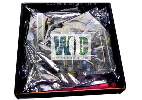
IS200VCMIH1C - Bus Master Controller

IS200VCMIH1C - Bus Master Controller IS200VCMIH1C - Bus Master Controller

World Of Controls understands the criticality of your requirement and works towards reducing the lead time as much as possible.

IS200VCMIH1C - Bus Master Controller is available in stock which ships the same day.

IS200VCMIH1C - Bus Master Controller comes in UNUSED as well as REBUILT condition.

To avail our best deals for IS200VCMIH1C - Bus Master Controller, contact us and we will get back to you within 24 hours.

SPECIFICATIONS

Part No.: IS200VCMIH1C
Manufacturer: General Electric
Country of Manufacture: United States of America (USA)
Board Type: 6U high VME board
SIze: 0.787 inch wide
Processor: Texas Instruments
Dual-port memory:32 Kbytes in 32 bit transfer configuration
SRAM:64k x 32
Flash memory:128k x 8
Product Type: Bus Master Controller
Availability: In Stock
Series: Mark VI

Functional Description

IS200VCMIH1C is a Bus Master Controller developed by GE. It is a part of Mark VI control system. The VCMI serves as a communication interface within the control system architecture. It facilitates seamless interaction between the controller and the I/O (Input/Output) boards, ensuring efficient data exchange and system control. The VCMI acts as the communication interface to the system control network, commonly referred to as IONet. By ensuring efficient data exchange between the controller and I/O boards, and by maintaining organized communication within the system control network (IONet), the VCMI helps maintain the integrity and performance of the control system. Its ability to manage board IDs further ensures that the system components are correctly identified and addressed, reducing the risk of communication errors and enhancing the overall robustness of the system.

Features

  • Communication Interface: It provides a reliable communication pathway, enabling the controller to send commands to and receive data from the various I/O boards. This ensures that the control system can effectively monitor and manage connected devices and sensors.
  • To IONet: The VCMI also connects to the IONet, the system control network, allowing for broader system integration and communication. This network connection is essential for coordinating activities across multiple control units and ensuring synchronized operations.
  • VME Bus Master: Functions as the VME (Versa Module Europa) bus master within the control and I/O racks. As the bus master, it oversees the data traffic on the VME bus, managing the timing and coordination of data exchanges to prevent conflicts and ensure smooth operation.
  • ID Management: Board and Terminal Board IDs: The VCMI manages the identification (IDs) for all the boards in the rack and their associated terminal boards. This management involves assigning and maintaining unique IDs for each board, facilitating accurate addressing and communication. Proper ID management is critical for the system to correctly identify and interact with each board, ensuring that commands and data are routed to the appropriate destinations.

Diagnostics

  • The system is equipped with robust diagnostic capabilities to ensure reliable operation and early detection of potential issues within the power supply and distribution networks. These diagnostics help maintain system integrity and prevent failures by providing continuous monitoring and alarming for various power supply parameters and signals.
  • The system continuously monitors the internal power supply buses, which include 5 V, 12 V, 15 V, and 28 V lines. Each of these power supply buses has alarm settings that are configurable according to system requirements. The default alarm thresholds are typically set at 3.5 percent for the 5 V, 12 V, and 15 V supplies. This means an alarm will be triggered if the voltage deviates by 3.5 percent from its nominal value. For the 28 V supplies, the alarm threshold is set at 5.5 percent, allowing for a slightly wider tolerance due to the higher voltage level.
  • In addition to monitoring internal power supply buses, the system integrates diagnostic signals from the Power Distribution Module (PDM), which is connected through the J301 connector. Key diagnostic parameters monitored include ground fault detection, which identifies any unintentional connections between the power bus and ground, potentially indicating insulation failures or wiring issues. The system also monitors over/under voltage conditions on the P125 V bus, helping to identify potential power supply instability or failures.
  • Two differential 5V DC analog inputs are monitored to ensure they remain within specified ranges, providing critical feedback for analog signal integrity. The P28A and PCOM inputs are used to monitor external circuits, ensuring that any connected external devices or systems operate correctly. Various digital inputs are also monitored for state changes, indicating the status of different system components or the occurrence of specific events.

The WOC team is always available to help you with your Mark VI requirements. For more information, please contact WOC.

Frequently Asked Questions

What is IS200VCMIH1C?
It is a bus master controller developed by GE under the Mark VI series.

What are the default alarm settings for the power supply buses?
The default alarm settings are typically set at 3.5 percent for the 5 V, 12 V, and 15 V supplies, and at 5.5 percent for the 28 V supplies.

What diagnostic signals are monitored from the Power Distribution Module (PDM)?
The VCMI system monitors several diagnostic signals from the PDM, including ground fault detection, over/under voltage on the P125 V bus, two differential 5V DC analog inputs, P28A and PCOM for external monitor circuits, and various digital inputs.

How does the system handle ground faults?
The system detects ground faults, which are unintentional connections between the power bus and ground, indicating potential insulation failures or wiring issues.

Why is it important to monitor over/under voltage on the P125 V bus?
Monitoring over/under voltage conditions on the P125 V bus helps identify potential power supply instability or failures, ensuring the system remains within safe operating parameters.