SPECIFICATIONS
Part No.: IS200VCCCH1BBA
Manufacturer: General Electric
Country of Manufacture: United States of America (USA)
Size: 26.04 cm high x 3.98 cm wide x 18.73 cm deep
Temperature: 0 to 60oC
Max response time on 25 ms
Max response time off 25 ms
Relay contact material Silver cad-oxide
Product Type: Discrete Input/Output Board
Availability: In Stock
Series: Mark VI
Functional Description
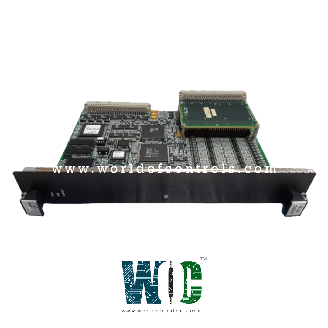
IS200VCCCH1BBA is a Discrete Input/Output Board developed by GE. It is part of the Mark VI series. Discrete Input/Output board, accompanied by its associated daughterboard, serves a critical role in managing discrete inputs and relay outputs within complex systems. The board, along with its daughterboard, is designed to accept a total of 48 discrete inputs and effectively control 24 relay outputs. These inputs and outputs are facilitated through four terminal boards, optimizing the management of various system functionalities.
Features
- Mounting and Connectivity: It is a double-width module specifically designed to mount within the VME (Versa Module Europa) I/O rack. The rack accommodates the VCCC board and features two sets of J3/J4 plugs for cable connections to the TBCI (Terminal Board for Control Inputs) and TRLY (Terminal Relay Board) terminal boards, ensuring seamless integration within the system.
- VCRC Alternative: Additionally, for more compact applications or as an alternative option, the VCRC board, a narrower single-slot board, can substitute the board. Both boards offer similar functionalities but differ in size and form factor.
- Voltage Compatibility Considerations: In 240 V AC applications, extreme caution must be exercised to avoid inadvertent cross-connections between the 240 V AC and DC voltages. Failure to observe this precaution can result in detrimental consequences due to voltage disparities:
- Potential for Voltage Exceedance: Cross-connecting 240 V AC and DC voltages inadvertently could lead to the peak voltage exceeding the Maximum Operating Voltage (MOV) rating, resulting in a catastrophic failure of the system components, particularly the MOVs.
- Understanding AC Grounded Neutral: The failure occurs primarily due to most AC supplies operating with a grounded neutral. In the event of an inadvertent connection between the 125 V DC and AC voltage sources, the sum of the AC peak voltage and the 125 V DC is applied to the MOVs connected between DC and ground.
- Difference in MOV Rating Tolerance: Notably, in 120 V AC applications, the MOV rating can withstand the peak voltage without causing a failure. However, in the case of higher 240 V AC applications, the MOVs might not tolerate the combined peak voltages, leading to potential system failures.
Relay Outputs
Relay Configuration
- Relay Assembly: Equipped to hold 12 plug-in magnetic relays, providing versatile control options within the system.
- Flexible Configuration: The first six relay circuits are adaptable and can be jumper-configured to accommodate dry, Form-C contact outputs, or for the purpose of driving external solenoids, enhancing flexibility in system usage.
- Power Sources: Field solenoid power is supported by a standard 125 V DC or 115 V AC source, with an optional 24 V DC source available. The power sources feature individual jumper-selectable fuses and on-board suppression, ensuring optimal power management and protection for field solenoids.
Relay Functionality
- Relay Types: The relays are classified into various types within the TRLYH1B-
- The first six relays can be configured as per requirements.
- Relays 7-11 are un-powered, offering isolated Form-C contacts.
- Relay 12 operates as an isolated Form-C contact, specially designated for unique applications like ignition transformers.
- Cable Functions: Cables are instrumental in carrying relay control signals and monitoring feedback voltages between the VCCC and TRLY, ensuring seamless communication and efficient relay operation.
- On-board Components: The relay drivers, fuses, and jumpers are strategically mounted on the relay board, ensuring convenient access and efficient relay management.
- Different types of relay boards, including TRLY, DRLY, and SRLY, can be effectively driven by this module, offering versatility in relay usage and control.
Fail-Safe Features
- Cable Disconnection: Fail-safe mechanisms are integrated to respond to cable disconnections. When a cable is unplugged, the inputs collectively vote to de-energize the corresponding relays, preventing unwanted or hazardous operational states due to disconnected cables.
- Communication Loss: Similarly, in cases where communication with the associated VME board is lost, the fail-safe mechanism triggers the de-energization of relays. This feature ensures that in the absence of communication, the system defaults to a safe state, preventing potential errors or unsafe operations.
The WOC team is always available to help you with your Mark VI requirements. For more information, please contact WOC.
Frequently Asked Questions
What is IS200VCCCH1BBA?
It is a Discrete Input/Output Board developed by GE under the Mark VI series.
How does the VCCC handle input voltages and ensure signal integrity?
It employs optical isolators to pass input voltages, ensuring signal integrity and isolation. It samples these signals at a specific frame rate optimized for control functions.
What is the sampling rate used for sequence of events (SOE) reporting within the VCCC?
For the sequence of events (SOE) reporting, the VCCC samples signals at a rapid rate of 1 millisecond, providing precise and detailed reporting of events occurring within the system.
How are signals transmitted from the board to the controller?
The component transfers the sampled signals over the VME backplane to the VCMI, which acts as an intermediary. The VCMI then forwards these signals to the controller for further processing and decision-making.
