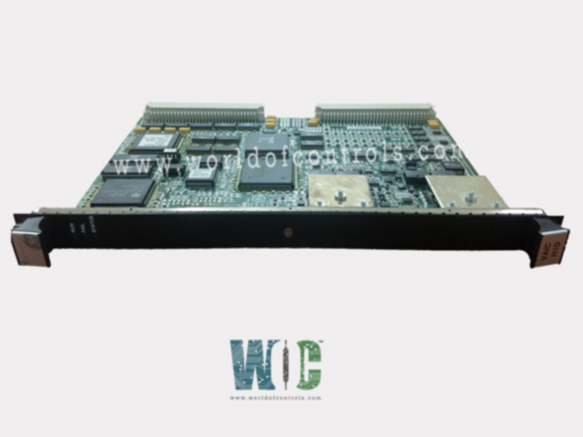
SPECIFICATIONS
Part No.: IS200VAICH1DA
Manufacturer: General Electric
Country of Manufacture: United States of America (USA)
Temperature: 0 to 60 °C
Size: 26.04 cm high x 1.99 cm wide x 18.73 cm deep
Product Type: Analog Input/Output Board
Availability: In Stock
Series: Mark VI
Functional Description
IS200VAICH1DA is an Analog Input/Output Board developed by GE. It is a part of Mark VI control system. The Analog Input/Output (VAIC) board is a versatile component designed to facilitate analog signal processing within control systems. The board accepts 20 analog inputs and controls 4 analog outputs, making it suitable for a wide range of monitoring and control applications. Each terminal board connected to the VAIC board accommodates 10 inputs and 2 outputs, providing scalability and flexibility in system configuration.
Features
- Upon receiving analog inputs, the board converts them into digital values. These digital values are then transferred over the VME backplane to the VCMI board and subsequently to the controller. For outputs, the board performs the reverse process, converting digital values into analog currents and driving them through the terminal board into the customer circuit.
- The board supports both simplex and Triple Modular Redundant (TMR) configurations, catering to different redundancy requirements and system architectures. In a TMR configuration, input signals on the terminal board are distributed to three separate VME board racks, each containing a VAIC.
- Output signals are generated using a proprietary circuit that utilizes all three VAICs, ensuring redundancy and fault tolerance. In the event of a hardware failure, the faulty VAIC is removed from the output, and the remaining two boards continue to produce the correct current. In a simplex configuration, the terminal board provides input signals to a single VAIC, which handles all output currents.
Redundancy and Fault Tolerance
- The TMR configuration enhances system reliability by providing redundancy in both input and output processing.
- By distributing input signals across multiple VAICs and using a proprietary circuit for output generation, the system can withstand hardware failures without compromising functionality. In simplex configurations, the system remains functional with a single VAIC handling both input processing and output generation.
Features
- Resolution: The input converter utilizes a 16-bit Analog-to-Digital (A/D) converter with 14-bit resolution. This high-resolution conversion capability enables precise measurement and conversion of analog signals.
- Scan Time: During normal operation, the scan time is set to 10 milliseconds (ms), equivalent to a scanning frequency of 100 Hz. This rapid scan rate allows for real-time monitoring and processing of input signals.
- High-Speed Scan for Inputs 1-4: Inputs 1 through 4 are specially designated for high-speed scanning, with a scanning frequency of 200 Hz. This accelerated scan rate ensures faster response and higher sampling frequency for critical input signals.
- Measurement Accuracy: The input converter boasts exceptional measurement accuracy, surpassing 0.1% of full scale. This high level of accuracy ensures precise and reliable measurement of analog input signals across the entire measurement range.
- Noise Suppression: Hardware filters are incorporated into the input circuits to suppress noise and interference effectively. The first ten circuits (J3) are equipped with a hardware filter featuring a single-pole down break at 500 radians per second (rad/sec). The remaining ten circuits (J4) feature a hardware filter with a two-pole down break at 72 and 500 rad/sec, providing enhanced noise suppression capabilities. Additionally, a configurable software filter is available, utilizing a two-pole low-pass filter with adjustable cutoff frequencies ranging from 0 to 12 Hz. This software filter allows for further customization of noise suppression based on specific application requirements.
- Common Mode Rejection: The input converter offers robust common mode rejection capabilities to minimize the impact of common mode voltages.
- AC Common Mode Rejection: Achieves 60 dB rejection at 60 Hz, with support for common mode voltages of up to ±5 volts.
- DC Common Mode Rejection: Provides 80 dB rejection with common mode voltages ranging from -5 to +7 peak volts, ensuring accurate measurement even in the presence of common mode voltage fluctuations.
The WOC team is always available to help you with your Mark VI requirements. For more information, please contact WOC.
Frequently Asked Questions
What is IS200VAICH1DA?
It is an analog input/output board developed by GE under the Mark VI series.
What happens if hardware limits are exceeded on an analog input?
If the hardware limits, preset near the ends of the operating range, are exceeded on any analog input, a logic signal is triggered, and the input is no longer scanned. Exceeding any hardware limit on an input generates a composite diagnostic alarm, L3DIAG VAIC, referring to the entire board. Detailed information about individual diagnostics is available from the toolbox. These diagnostic signals can be individually latched and reset using the RESET DIA signal.
How are system limits checked on analog inputs?
Each analog input undergoes system limit checking based on configurable high and low levels. These limits can be set to generate alarms and can be configured for enable/disable, as well as latching/non-latching. The RESET SYS signal resets inputs that are out of limits.
How are faults handled in Triple Modular Redundant (TMR) systems?
In TMR systems, if one signal deviates from the voted value (median value) by more than a predetermined limit, a fault is created. This early indication of a problem developing in one channel helps maintain system integrity and reliability.
What are monitored in the VAIC outputs?
The VAIC monitors D/A outputs, output currents, total current, suicide relays, and 20/200 mA scaling relays for reasonability. Any discrepancies can trigger fault conditions, alerting operators to potential issues.
