SPECIFICATIONS
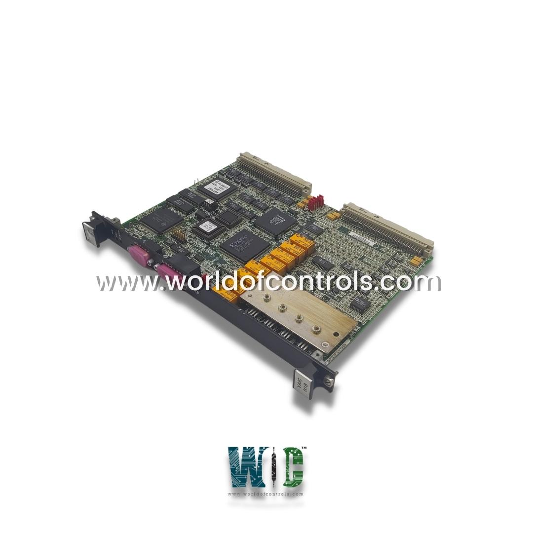
Part No.: IS200VAICH1BBB
Manufacturer: General Electric
Country of Manufacture: United States of America (USA)
Temperature: 0 to 60 oC
Size: 26.04 cm high x 1.99 cm wide x 18.73 cm deep
Power consumption Less than 31 MW
Common mode voltage range: 5 V
Number of channels: 24
Product Type: Analog Input Board
Availability: In Stock
Series: Mark VI
Functional Description
IS200VAICH1BBB is an analog input board developed by GE. It is a part of Mark VI control system. It is designed to handle a analog signals and facilitate seamless communication between the field devices and the controller. VAIC is capable of accommodating up to 20 analog inputs, allowing for connectivity with a range of sensors and instruments. Moreover, it manages the operation of four analog outputs, offering the versatility to adjust external devices or systems according to processed input data.
Features
- Terminal Board Integration: Each Analog Input terminal board is equipped to handle ten inputs and two outputs, streamlining the connection of field devices to the control system. These terminal boards serve as the interface between the physical sensors or instruments and the VAIC processor board located within the VME rack.
- Data Conversion and Transmission: Upon receiving analog signals from the field devices, the VAIC performs analog-to-digital conversion, transforming the input values into digital data that can be processed by the controller. The digital values are then transmitted over the VME backplane to the VCMI (VME Communication Interface) board, which acts as a bridge between the control system components. From the VCMI board, the digital data is relayed to the controller, where it can be utilized for various control and monitoring functions.
- Terminal Board Requirements: To accommodate the full complement of 20 analog inputs, the VAIC necessitates the use of two terminal boards, each capable of handling ten inputs. This modular setup allows for scalability and flexibility in system configuration, enabling seamless expansion or modification of input channels as needed.
- Output Signal Generation: In addition to processing input data, the VAIC is responsible for generating analog output signals based on digital control commands received from the controller. These output signals are converted from digital to analog format by the VAIC and subsequently transmitted through the terminal board to external circuits or devices for further action.
Installation
- Power Down the VME Processor Rack: Begin by shutting down the VME processor rack to ensure safe installation procedures.
- Slide in the Board: Carefully insert the board into the designated slot in the VME rack. Use both hands to guide the board into place, ensuring that the edge connectors align properly.
- Secure the Board: Once the board is fully inserted, press the top and bottom levers to secure it in place. Make sure the edge connectors are firmly seated in their slots.
- Tighten Captive Screws: Use captive screws located at the top and bottom of the VAIC board's front panel to secure it firmly in the rack.
Fault detection
- Analog Input Out of Limits: The system actively monitors analog inputs for any deviations beyond predetermined thresholds, signaling potential issues if any input values exceed specified limits.
- Monitor D/A Outputs and Currents: Constant surveillance is maintained over the digital-to-analog (D/A) outputs and their respective currents. Any irregularities or discrepancies in output currents are promptly flagged for investigation.
- Suicide Relay and Scaling Relays Monitoring: The health of critical components such as the suicide relay and scaling relays is continuously monitored. This involves checking for proper functioning and response within predefined parameters.
- Comparison with Voted Value: Input signals are rigorously compared with their corresponding voted values to ensure consistency and accuracy. Any deviations beyond the predetermined tolerance levels trigger alerts for further assessment.
- TMR Limit Verification: The system verifies the difference between input signals and the TMR (Triple Modular Redundant) limit to ensure compliance with safety standards and operational requirements.
- Detection of Failed I/O Chip: Comprehensive diagnostics include the detection of failed I/O chips, which can impact the reliability and performance of the system. Any instances of failed I/O chips are promptly identified and reported for immediate action.
The WOC team is always available to help you with your Mark VI requirements. For more information, please contact WOC.
Frequently Asked Questions
What is IS200VAICH1BBB?
It is an analog input board developed by GE under the Mark VI series.
What are the hardware limit checking features for analog inputs on the board?
Each analog input on the board incorporates hardware limit checking with preset high and low levels. These levels are established near the ends of the input's operational range. If an input surpasses these limits, a logic signal is activated, and the input ceases to be scanned.
How does the system handle inputs that exceed hardware limits?
When an input exceeds its hardware limits, a composite diagnostic alarm, known as L3DIAG VAIC, is generated, referring to the entire VAIC board. This alarm consolidates information about inputs with limit breaches. Detailed diagnostics for individual inputs can be accessed via the toolbox interface.
Can diagnostic signals be managed individually?
Yes, diagnostic signals can be individually latched, allowing for precise tracking of specific issues. These signals can then be reset using the RESET DIA signal, facilitating efficient troubleshooting and maintenance procedures.
