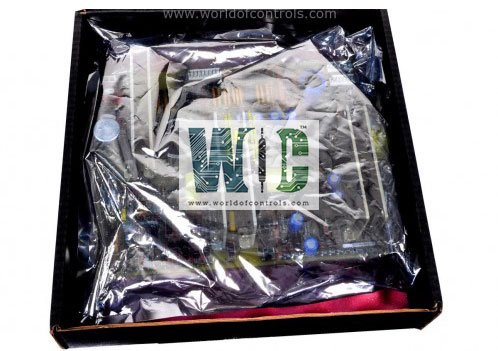
World Of Controls understands the criticality of your requirement and works towards reducing the lead time as much as possible.
IS200UCVBG1A - Double-Slot Controller Board is available in stock which ships the same day.
IS200UCVBG1A - Double-Slot Controller Board comes in UNUSED as well as REBUILT condition.
To avail our best deals for IS200UCVBG1A - Double-Slot Controller Board, contact us and we will get back to you within 24 hours.
Part No.: IS200UCVBG1A
Manufacturer: General Electric
Country of Manufacture: United States of America (USA)
Number of channels: 8
Span: 0.3532 to 4.054 V
Temperature: -30 to +65 oC
Technology:Surface mount
Product Type: Double-Slot Controller Board
Availability: In Stock
Series: Mark VI
IS200UCVBG1A is a double-slot controller board developed by GE. It is a part of the Mark VI control system. UCVB is designed to fulfill essential functions with precision and reliability. Engineered as a double-slot board, it incorporates a formidable 133 MHz Intel Pentium processor, a cornerstone of computational efficiency and performance. Supporting the processor's operations are 4 MB of flash memory and 16 MB of DRAM, ensuring sufficient storage and memory capacity for seamless execution of tasks and processes.
The Ethernet interface of the system utilizes Thinwire 10Base2 technology, facilitated by a BNC connector. This interface serves as the backbone for communication within the system, facilitating seamless data exchange and control processes.
The system features two COM ports, each utilizing micro-miniature 9-pin D connectors, offering additional connectivity options for specific tasks:
The WOC team is always available to help you with your Mark VI requirements. For more information, please contact WOC.
What is IS200UCVBG1A?
It is a double-slot controller board developed by GE under the Mark VI series.
What do the status LEDs on the UCVB indicate?
It features a double column of eight status LEDs, which serve as indicators of the controller's operating status. Under normal operation, these LEDs are sequentially turned on in a rotating pattern, indicating that the controller is functioning correctly.
How does the component alert users to error conditions?
In the event of an error condition, the status LEDs display a flashing error code. This error code is designed to identify the specific problem that has occurred, enabling users to diagnose and address the issue promptly.
What is the significance of the rotating pattern of LEDs during normal operation?
The rotating pattern of LEDs during normal operation provides users with a visual confirmation that the controller is functioning as intended. This sequential activation of LEDs indicates that the system is operational and ready for use.
How should users interpret the flashing error code displayed by the status LEDs?
The flashing error code displayed by the status LEDs indicates the nature of the error condition that has occurred within the system. By referencing the error code, users can determine the specific problem and take appropriate corrective action to resolve it.