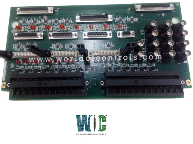
SPECIFICATIONS
Part No.: IS200TVBAH2ABB
Manufacturer: General Electric
Country of Manufacture: United States of America (USA)
Output: -24.5V (-23 to –26)
Iout: 12mA maximum
Product Type: Vibration Terminal Board
Availability: In Stock
Series: Mark VIe
Functional Description
IS200TVBAH2ABB is a vibration terminal board developed by GE. It is part of the Mark VIe series. The Vibration Terminal Board (TVBA) in Mark VIe systems serves as a critical signal interface component for the Mark VIe I/O pack PVIB. In conjunction with the VVIB board in Mark VI systems, the TVBA facilitates seamless signal processing and transmission.
Features
- Functionality: Specifically designed to accommodate various types of probes, including seismic (velocity), Proximitors, Velomitors, and accelerometer-type probes. Its primary function is to provide a direct interface for these probes while ensuring signal suppression and electromagnetic interface (EMI) protection for each input signal.
- Signal Processing:
Each input signal connected undergoes signal suppression and EMI protection measures, safeguarding against interference and ensuring signal integrity. Additionally, signals are linked to a pull-up bias, enabling the detection of open circuits, thereby enhancing system reliability.
- Connection Interface: Interfaces with the Mark VIe I/O packs via a 37-pin connector, facilitating the seamless transmission of processed signals to the I/O packs for further processing and control.
- Application Flexibility: It can be deployed for both simplex and Triple Modular Redundant (TMR) configurations. In TMR setups, the TVBA fans the signal to three I/O packs, enhancing redundancy and fault tolerance in critical applications.
Installation
- Sensor Input Configuration: It accommodates up to 14 sensor inputs, which are directly wired to two I/O terminal blocks. Each block is securely fastened with two screws and features 24 terminals capable of accepting wires up to 12 AWG. Adjacent to each terminal block, a shield termination attachment point is provided, enhancing signal integrity.
- Input Channels 1 through 8: These channels support a variety of sensors including Proximitors, Seismics, Accelerometers (limited to channels 1, 2, and 3), and Velomitors. Each channel is equipped with a current-limited -24V power supply, ensuring consistent and reliable operation. Configurations for open circuit check support and constant current feed for Velomitors are facilitated by JPxA jumpers. Additionally, JPxB is utilized to configure the JA1 and JB1 outputs for compatibility with the Bently Nevada 3500 rack. JPxC provides flexibility in configuring PR0xL as open for true differential input or connecting PR0xL to PCOM for a -24V return.
- Input Channels 9 through 12: These channels are dedicated exclusively to Proximitors sensors. Similar to channels 1 through 8, each channel is equipped with a current-limited -24V power supply, ensuring consistent operation. However, no jumper configuration is required for these channels.
- Input Channel 13: Channel 13 supports Proximitors or Keyphasor proximity sensors. Like the previous channels, it features a current-limited -24V power supply. No jumper configurations are necessary for this channel.
- -28V Power Supply Board (WNPS): The WNPS serves a crucial role in the installation by converting the +28V input from the PVIB to the -28V required by the current-limited -24V outputs. Each PVIB is accompanied by one WNPS, ensuring independent +28V inputs and a common -28V bus for all three WNPSs, thereby optimizing power distribution and efficiency.
The WOC team is always available to help you with your Mark VIe requirements. For more information, please contact WOC.
Frequently Asked Questions
What is IS200TVBAH2ABB?
It is a vibration terminal board developed by GE under the Mark VIe series.
What function does the board serve regarding open circuit detection?
It is equipped with open circuit detection capabilities for each vibration input. If any of the inputs register an out-of-range voltage, the I/O processor generates a diagnostic alarm (fault) to alert users of the issue.
How does the TVBA ensure proper cable connection and compatibility?
Each cable connector on the terminal board features its own unique ID device. This ID device, a read-only chip, contains essential information such as the terminal board serial number, board type, revision number, and connector location (JR, JS, JT). When the I/O processor interrogates this chip and detects a mismatch, indicating a hardware incompatibility, it triggers a fault to prompt appropriate action.
What is the purpose of the ID device on the cable connectors?
The ID device serves as a means of verifying proper cable connection and ensuring compatibility between components. By storing crucial information about the terminal board and connector, it allows the I/O processor to identify any discrepancies and flag them as hardware incompatibility faults, thereby maintaining system integrity and reliability.
