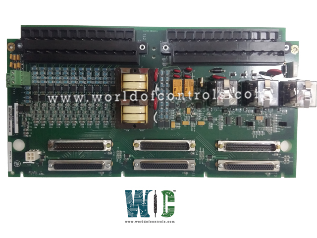
IS200TTURH1CFD - Turbine Specific Primary Trip Board

IS200TTURH1CFD - Turbine Specific Primary Trip Board IS200TTURH1CFD - Turbine Specific Primary Trip Board

World Of Controls understands the criticality of your requirement and works towards reducing the lead time as much as possible.

IS200TTURH1CFD - Turbine Specific Primary Trip Board is available in stock which ships the same day.

IS200TTURH1CFD - Turbine Specific Primary Trip Board comes in UNUSED as well as REBUILT condition.

To avail our best deals for IS200TTURH1CFD - Turbine Specific Primary Trip Board, contact us and we will get back to you within 24 hours.

SPECIFICATIONS

Part No.: IS200TTURH1CFD
Manufacturer: General Electric
Country of Manufacture: United States of America (USA)
Speed sensor range MPU pulse rate range: 2 Hz to 20 kHz
Speed sensor accuracy MPU pulse rate accuracy: 0.05percent
Speed sensor input circuit sensitivity: 27 mV pk
Size: 8.26 cm High x 4.19 cm Wide x 12.1 cm Deep
Temperature: -30 to 65 oC
Technology: Surface mount
Product Type: Turbine Specific Primary Trip Board
Availability: In Stock
Series: Mark VI

Functional Description

IS200TTURH1CFD is a Turbine Specific Primary Trip Board developed by GE. It is a part of the Mark VI control system. The Primary Turbine Protection Input terminal board is an essential component designed to interface with the VTUR module, facilitating comprehensive turbine protection functionalities. PTURH1A is compatible with the Turbine Terminal Board TTURH1C and the STUR board, but it is not compatible with the DIN rail-mounted DTUR or other TTUR boards.

Input and Output Configurations

  • Passive Pulse Rate Devices: PTTUR accommodates twelve passive pulse rate devices strategically positioned to sense a toothed wheel, enabling precise measurement of turbine speed. This input is pivotal for monitoring turbine rotational dynamics.
  • Voltage Signals: The board efficiently captures generator voltage and bus voltage signals transmitted from potential transformers. These voltage readings are fundamental for assessing the electrical health and performance of the turbine and associated systems.
  • 125 V DC Output: PTTUR features a dedicated 125 V DC output channel designed to supply power to the main breaker coil, facilitating automatic generator synchronizing. This functionality enhances operational efficiency and system reliability during synchronization procedures.
  • Shaft Voltage and Current Sensors: Inputs from shaft voltage and current sensors are meticulously processed by PTTUR to measure induced shaft voltage and current. These measurements offer critical insights into the mechanical and electrical conditions of the turbine assembly.

Relay Configurations

  • K25 Relay: This relay, along with K25P and K25A, must close collectively to provide the necessary 125 V DC power required to engage the main breaker, denoted as 52G. This failsafe mechanism enhances system reliability and safety.
    Connector Configuration
  • In standard configurations, the speed signal cable to VTUR is routed through the JR5 connector, while other critical signals utilize the JR1 connector. For systems employing Triple Modular Redundancy (TMR), signals are intelligently distributed across multiple connectors, including JR5, JS5, JT5, JR1, JS1, and JT1, ensuring redundancy and fault tolerance.

Installation

  • Step 1: Mounting the Terminal Board
    • Securely mount the designated terminal board in the desired location within the system enclosure.
    • Ensure that the board is positioned securely and aligned correctly for optimal functionality.
  • Step 2: Plugging in PTUR I/O Packs
    • Depending on the system configuration, plug in either one PTUR I/O pack for simplex operation or three packs for Triple Modular Redundancy (TMR) setup.
    • Connect these packs directly into the corresponding terminal board connectors.
  • Step 3: Securing the Packs
    • Mechanically secure the PTUR I/O packs using the provided threaded studs located adjacent to the Ethernet ports. These studs should be inserted into a mounting bracket specific to the terminal board type. Adjust the bracket's position to prevent any right-angle force on the DC62 connector between the pack and the terminal board. This adjustment is typically required only once during the product's lifecycle.
  • Step 4: Connecting Ethernet Cables
    • Plug in one or two Ethernet cables, depending on the system's configuration.
    • The PTUR pack can operate over either port. If utilizing dual connections, it's standard practice to connect ENET1 to the network associated with the R controller.
  • Step 5: Applying Power
    • Apply power to the PTUR pack by securely plugging in the connector located on the side of the pack.
    • Note that it's not necessary to insert this connector with the power removed from the cable
    • I/O pack incorporates inherent soft-start capability to regulate current inrush during power application.
  • Step 6: Configuration
    • Configure the PTUR I/O pack as per the system's requirements and specifications.
    • Adjust settings and parameters as necessary to ensure optimal performance and compatibility with the overall system architecture.

The WOC team is always available to help you with your Mark VI requirements. For more information, please contact WOC.

Frequently Asked Questions

What is IS200TTURH1CFD?
It is a Turbine Specific Primary Trip Board developed by GE under the Mark VI series.

How does the processor board initialize upon power application in the I/O pack?
Upon application of input power, the processor board undergoes a sequence of actions facilitated by a soft-start circuit. Initially, the voltage available on the processor board gradually ramps up. Subsequently, the local power supplies are sequenced on, and the processor reset is removed. Following this, the processor executes self-test routines and proceeds to load application code specific to the I/O pack type from flash memory.

How does the application code ensure compatibility with the I/O pack components?
The application code reads board ID information to verify the correct matching of application code, acquisition board, and terminal board. This validation process ensures that the components are appropriately configured and compatible for seamless operation.

What steps are taken to establish network communication after power-up?
After completing the initialization procedures, the processor endeavors to establish Ethernet communications. This process begins with a request for a network address, which is facilitated through the industry-standard dynamic host configuration protocol (DHCP). The unique identification read from the terminal board aids in this communication setup.

What tasks does the processor execute post-Ethernet initialization?
Upon successful Ethernet initialization, the processor proceeds to program the on-board logic, execute the loaded application, and enable the acquisition board to commence its operational functions. This comprehensive process ensures the efficient and effective functioning of the I/O pack within the system.