World Of Controls understands the criticality of your requirement and works towards reducing the lead time as much as possible.
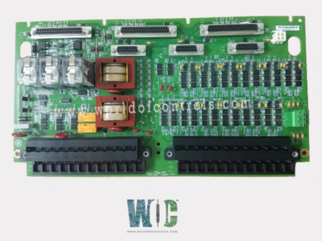
IS200TTURH1CAA - Thermocouple Input Terminal Board is available in stock which ships the same day.
IS200TTURH1CAA - Thermocouple Input Terminal Board comes in UNUSED as well as REBUILT condition.
To avail our best deals for IS200TTURH1CAA - Thermocouple Input Terminal Board, contact us and we will get back to you within 24 hours.
SPECIFICATIONS:
Part Number: IS200TTURH1CAA
Manufacturer: General Electric
Series: Mark VIe
Product Type: Thermocouple Input Terminal Board
Operating System: QNX
Power Requirements: +5 V dc, 6 A
Number of input channels: 12
Number of outputs: 125 V dc
Trip Solenoid Rating: 125 V dc
Power supply voltage: 28 V dc
Voltage Range: 18 - 32 VDC
Mounting: DIN-rail mounting
Technology: Surface mount
Operating temperature: 40 to 70°C
Size: 33.0 cm high x 17.8 cm
Repair: 3-7 Day
Availability: In Stock
Country of Origin: United States
Manual: GEH-6721D
FUNCTIONAL DESCRIPTION:
IS200TTURH1CAA is a Thermocouple Input Terminal Board manufactured and designed by General Electric as part of the Mark VIe Series used in GE Distributed Turbine Control Systems. TTUR has three relays, K25, K25P, and K25A, that all have to close to provide 125 V dc power to close the main breaker 52G. The signals to PTUR use the PR3 and JR4 connectors for simplex systems. For TMR systems, signals fan out to the PR3, PS3, PT3, JR4, JS4, and JT4 connectors. TTURH1C supports the connection of TRPG, TRPS, and TRPA boards and accommodates the PTUR I/O pack. The turbine terminal board, TTURH1C, works with the PTUR turbine I/O packs as part of the Mark VIe system. The inputs and outputs are as follows:
INSTALLATION:
Pulse rate pick-ups, shaft pick-ups, potential transformers, and the breaker relay are wired to the two terminal blocks TB1 and TB2. Each block is held down with two screws and has 24 terminals accepting up to #12 AWG wires. A shield terminal strip attached to the chassis ground is located immediately to the left of each terminal block. Jumpers JP1 and JP2 select either simplex or TMR for relay drivers K25 and K25P. Removing wire jumper WJ1 isolates the K25A control line to the TRPX board. TB3 is for optional TTL connections to active speed pickups; these devices require an external power supply. Simplex systems use cable connectors PR3 and JR4. TMR systems use all six cable connectors.
OPERATION:
In the simplex application, up to four pulse rate signals may be used to measure turbine speed. Generator and bus voltages are brought into TTUR for automatic synchronizing in conjunction with PTUR, the turbine controller, and the excitation system. TTUR has a permissive generator synchronizing relays and controls the main breaker relay coil 52G. In TMR applications, all inputs, except speed, fan to the three PTUR packs. Control signals coming into TTUR from R, S, and T are voted before they actuate permissive relays K25 and K25P. Relay K25A is controlled by the PPRO and TREG boards through J8.
WOC has the largest stock of OEM replacement parts for GE Distributed Turbine Control Systems. We can also repair your faulty boards and supply unused and rebuilt boards backed up with a warranty. Our team of experts is available round the clock to support your OEM needs. Our team of experts at WOC is happy to assist you with any of your automation requirements. For pricing and availability on parts and repairs, kindly contact our team by phone or email.
What is a Thermocouple Input Terminal Board?
A Thermocouple Input Terminal Board is a circuit board designed to interface multiple thermocouples with a data acquisition system, PLC, or temperature controller. It provides a structured connection for thermocouple sensors, ensuring accurate temperature readings while offering signal conditioning, cold junction compensation, and noise filtering.
What types of thermocouples are supported?
Most Thermocouple Input Terminal Boards support common thermocouple types such as J, K, T, E, N, R, S, and B. The compatibility of thermocouple types depends on the board model and the system it is designed to work with. Each thermocouple type has a unique temperature range and sensitivity, making it suitable for different industrial applications.
What is the output signal format?
Thermocouple Input Terminal Boards typically output signals in various formats, including millivolt (mV) signals, 4-20mA current loops, or digital data via communication protocols such as Modbus, RS485, or Ethernet. The output format depends on the system requirements and the type of data acquisition being used.