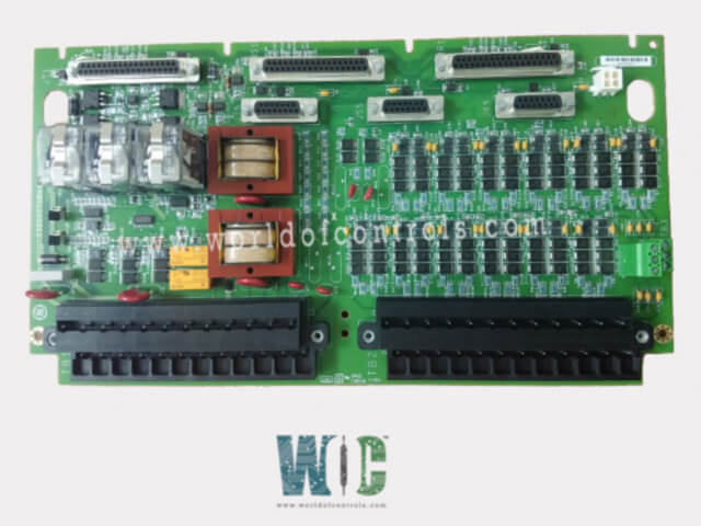
SPECIFICATIONS
Part No.: IS200TTURH1BED
Manufacturer: General Electric
Country of Manufacture: United States of America (USA)
Size: 33.0 cm high x 17.8 cm wide
Technology: Surface mount
Temperature Operating: -30 to 65 oC
Product Type: Protection Input turbine terminal Board
Availability: In Stock
Series: Mark VI
Functional Description
IS200TTURH1BED is a Protection Input turbine terminal Board developed by GE. It is a part of the Mark VI control system. It interfaces with the turbine I/O processor and plays a key role in managing inputs and outputs related to turbine operations. This board is integral for ensuring accurate measurement and control of various turbine parameters.
Inputs and Outputs
- The TTUR is connected to twelve passive pulse rate devices. These devices utilize a toothed wheel to measure the turbine’s rotational speed. The pulse signals generated by these sensors are used to calculate the turbine speed precisely, which is essential for monitoring and controlling turbine performance.
- The TTUR handles generator and bus voltage signals, both of which are obtained from potential transformers. These transformers reduce high voltages to lower, manageable levels, providing accurate voltage readings crucial for the safe and efficient operation of the generator and bus systems.
- A 125 V DC output is provided by the TTUR to the main breaker coil. This output is necessary for automatic generator synchronizing. It enables the main breaker to close and align the generator with the power grid, ensuring seamless integration and operation.
- The TTUR receives inputs from shaft voltage and current sensors. These sensors measure the induced voltage and current in the turbine’s shaft, which are vital for assessing the turbine’s operational health and ensuring optimal performance.
Relay Functions
- K25 Relay: This relay, along with the others, must close to supply the 125 V DC power needed for the main breaker to operate.
- K25P Relay: Part of the relay trio, this relay ensures the proper functioning of the main breaker.
- K25A Relay: The K25A relay must also close to provide the necessary power to the main breaker, completing the circuit.
Signal Connections
- The speed signal cable, connected to the VTUR, uses the JR5 connector. This connection is responsible for transmitting speed data from the pulse rate devices to the turbine control system, allowing for accurate speed monitoring.
- Signals related to generator and bus voltage, as well as shaft measurements, are routed through the JR1 connector. This connector ensures that all critical operational data is communicated effectively to the I/O processor.
Installation
The installation of the turbine terminal board (TTUR) is crucial for ensuring the accurate operation and reliability of the turbine control system. This process involves connecting various components, configuring jumpers, and making the necessary cable connections. Each step must be performed carefully to maintain the system's efficiency and performance.
- Wiring Terminal Blocks: Magnetic pickups, shaft pickups, potential transformers, and breaker relays are wired to two I/O terminal blocks, labeled TB1 and TB2. Each terminal block is secured with two screws and features 24 terminals that can accommodate wires up to 12 AWG (American Wire Gauge). These terminal blocks facilitate organized and secure connections for various sensors and control devices, ensuring that all wiring is properly managed and connected. Adjacent to each terminal block is a shield termination strip attached to the chassis ground. This strip is essential for grounding the shielded cables connected to the TTUR. Proper grounding helps reduce electrical noise and interference, which is critical for maintaining signal integrity and ensuring reliable system operation.
- Jumper Configuration: Jumpers JP1 and JP2 are used to select the operating mode for relay drivers K25 and K25P. These jumpers allow the user to choose between Simplex Modular eXtra (SMX) and Triple Modular Redundancy (TMR) configurations. SMX is suitable for standard, non-redundant operation, while TMR provides a high-redundancy configuration that enhances system reliability by incorporating redundant components.
- TTL Connections: TB3 is designated for optional TTL (Transistor-Transistor Logic) connections to active speed pickups. TTL connections require an external power supply to function properly. This terminal block allows for the integration of TTL-compatible sensors, which can offer additional options for precise speed measurement and improved performance.
- Cable Connectors: For Simplex systems, the installation utilizes two primary cable connectors: JR5 and JR1. The JR5 connector is used for speed signal connections, while the JR1 connector handles other essential signals, including voltage and shaft measurements.
The WOC team is always available to help you with your Mark VI requirements. For more information, please contact WOC.
Frequently Asked Questions
What is IS200TTURH1BED?
It is a Protection Input turbine terminal Board developed by GE under the Mark VI series.
What is the function of TB3 in the installation?
TB3 is used for optional TTL connections to active speed pickups. TTL connections require an external power supply to operate. This terminal block allows you to integrate TTL-compatible sensors for enhanced speed measurement capabilities.
Which cable connectors are used for Simplex systems?
Simplex systems use two primary cable connectors- JR5 and JR1. JR5 is used for speed signal connections, while JR1 handles other critical signals, including voltage and shaft measurements.
What connectors are required for TMR systems?
TMR systems require all six cable connectors- JR5, JR1, JS5, JS1, JT5, and JT1. These connectors ensure comprehensive signal distribution and system redundancy, providing enhanced reliability.
