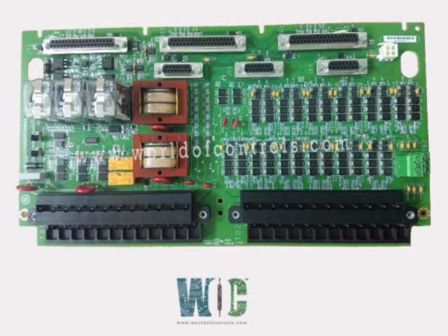
SPECIFICATIONS
Part No.: IS200TTURH1BEC
Manufacturer: General Electric
Country of Manufacture: United States of America (USA)
Size: 10.16 cm wide x 33.02 cm high
Temperature: -30 to 65oC
Technology: Surface-mount
Product Type: Primary Protection Input Board
Availability: In Stock
Series: Mark VI
Functional Description
IS200TTURH1BEC is a Primary Protection Input Board developed by GE. It is a part of the Mark VI control system. The board serves as an interface within the turbine I/O processor, offering various inputs and outputs crucial for turbine control and monitoring.
Inputs for Turbine Speed Measurement
- The Turbine Terminal Unit (TTUR) is equipped with 12 passive pulse rate devices specifically designed to sense the toothed wheel of the turbine, facilitating accurate measurement of its rotational speed. These devices play a critical role by generating electrical pulses in response to the passage of teeth or markings on the wheel as the turbine rotates, providing a reliable means to monitor and determine the turbine's speed.
- The collective output of these devices ensures accuracy and redundancy in speed measurement, feeding essential data into the control system for effective monitoring and management of turbine operations.
Voltage Signals Monitoring
- The TTUR actively monitors the generator voltage, a key electrical parameter representing the voltage generated by the turbine's generator. This signal provides insights into the voltage output generated by the turbine during its operation.
- Alongside generator voltage, the TTUR also monitors the bus voltage signal. Bus voltage refers to the voltage levels present within the electrical bus or distribution system. It provides an overview of the voltage levels across the broader electrical infrastructure connected to the turbine.
- These voltage signals are typically obtained through potential transformers, which are devices specifically designed to measure and transform high voltage levels into lower, measurable levels suitable for monitoring and analysis.
- The TTUR's role in monitoring these voltage signals is pivotal for ensuring the stability, reliability, and safety of the electrical systems associated with the turbine.
- Constant oversight of generator and bus voltages allows for real-time analysis of voltage levels. Deviations from expected or safe voltage ranges can trigger alerts or enable corrective actions to maintain operational stability and prevent potential damage to equipment.
- The monitored voltage signals are integrated into the broader control and monitoring systems. This integration enables real-time data analysis, facilitating informed decision-making and prompt responses to voltage-related anomalies or fluctuations.
Signal Connectivity
- The speed signal cable designated for VTUR utilization is connected through the JR5 connector.
- Other signals, excluding the speed signal, are routed through the JR1 connector.
- For Triple Modular Redundancy (TMR) systems, signals are distributed across multiple connectors: JR5, JS5, JT5, JR1, JS1, and JT1, ensuring redundancy and failover capabilities for these critical signals.
Other Features
- Output for Main Breaker Control: Provides a 125 V dc output intended for the main breaker coil. This output is utilized for automatic generator synchronization, facilitating synchronized operations.
- Shaft Voltage and Current Sensors: Accepts inputs from sensors measuring induced shaft voltage and current, aiding in the measurement and monitoring of these crucial parameters.
- Relays for Main Breaker Control (K25, K25P, K25A): Features three relays - K25, K25P, and K25A - all essential for a coordinated operation to supply 125 V dc power necessary to close the main breaker 52G.
Installation Procedure
- Component Identification: Gather the necessary components including magnetic pickups, shaft pickups, potential transformers, and breaker relays.
- Terminal Blocks: Two I/O terminal blocks, TB1 and TB2, are utilized for wiring. Each block is securely fastened with two screws and features 24 terminals capable of accepting wires up to 12 AWG. Adjacent to each terminal block is a shield termination strip connected to the chassis ground, ensuring proper grounding for the system.
- Relay Driver Selection: Jumpers JP1 and JP2 are utilized to select between SMX and TMR options for relay drivers K25 and K25P, providing flexibility based on system requirements.
- Optional TTL Connections: TB3 serves as a dedicated terminal block for optional TTL connections to active speed pickups. These connections may require an external power supply for operation.
- System Differentiation: Cable connectors JR5 and JR1 are used for simplex systems, while TMR systems utilize all six cable connectors, indicating a distinction in the wiring configuration based on the system's complexity and functionality.
- Wiring: Carefully wire the components to their respective terminal blocks, ensuring proper connections according to the system's specifications and requirements. Pay close attention to jumper settings and terminal assignments to avoid errors during installation.
- Testing: Once the wiring is complete, conduct thorough testing to verify the functionality of the installed components and ensure they operate as intended. This step is crucial for identifying any potential issues or discrepancies that may require further adjustment or troubleshooting.
The WOC team is always available to help you with your Mark VI requirements. For more information, please contact WOC.
Frequently Asked Questions
What is IS200TTURH1BEC?
It is a primary protection input board developed by GE under the Mark VI series.
How many pulse rate signals are utilized in a simplex application to measure turbine speed?
In a simplex setup, up to four pulse rate signals may be employed for turbine speed measurement, ensuring accuracy in speed monitoring.
What key functions does TTUR perform concerning synchronization and control?
It incorporates permissive generator synchronizing relays and controls the main breaker relay coil 52G, enabling coordinated and safe turbine operations.
