SPECIFICATIONS
Part No.: IS200TTURH1BCC
Manufacturer: General Electric
Country of Manufacture: United States of America (USA)
Size: 33.0 cm high x 17.8 cm wide
Technology: Surface mount
Temperature Operating: -30 to 65 oC
Number of outputs: Generator breaker coil, 5A at 125 V dc
Power supply voltage: Nominal 125 V dc to breaker coil
MPU pulse rate range: 2 Hz to 20 kHz
MPU pulse rate accuracy: 0.05 percent of reading
Product Type: Primary Protection Input Board
Availability: In Stock
Series: Mark VI
Functional Description
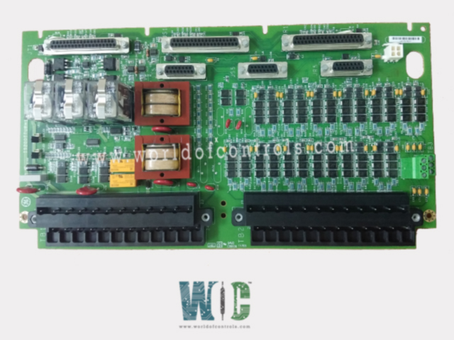
IS200TTURH1BCC is an Primary Protection Input Board developed by GE. It is a part of Mark VI control system. The Turbine Terminal Board is a component that interfaces with the turbine I/O processor, facilitating various inputs and outputs essential for turbine operation. TTUR features three relays K25, K25P, and K25A. The closure of all these relays is necessary to provide 125 V DC power required for closing the main breaker 52G, ensuring seamless operation.
Inputs and Outputs
- Pulse Rate Devices: Incorporates 12 passive pulse rate devices that sense a toothed wheel, enabling the measurement of turbine speed.
- Generator and Bus Voltage Signals: Signals from potential transformers are utilized to monitor generator voltage and bus voltage.
- 125 V DC Output: Provides a 125 V DC output specifically designated for the main breaker coil, essential for automatic generator synchronizing.
- Shaft Voltage and Current Sensors: Inputs from shaft voltage and current sensors are processed by TTUR to measure induced shaft voltage and current.
Connector Usage
- The speed signal cable destined for VTUR employs the JR5 connector.
- Other signals utilize the JR1 connector.
- For Triple Modular Redundancy (TMR) systems, signals fan out to various connectors, including JR5, JS5, JT5, JR1, JS1, and JT1, ensuring redundancy and system reliability.
Installation
Proper installation of turbine components is crucial for optimal performance and safety. Here's a detailed guide on how to install magnetic pickups, shaft pickups, potential transformers, and breaker relays, along with the necessary wiring to I/O terminal blocks:
- Wiring Configuration:
- Magnetic pickups, shaft pickups, potential transformers, and breaker relays are wired to two I/O terminal blocks, namely TB1 and TB2.
- Each terminal block is securely fastened with two screws and accommodates up to #12 AWG wires.
- Adjacent to each terminal block, a shield termination strip connected to chassis ground ensures proper grounding for enhanced safety and signal integrity.
- Jumper Selection:
- Jumpers JP1 and JP2 are provided to select between SMX (Simplex) or TMR (Triple Modular Redundancy) configurations for relay drivers K25 and K25P.
- Proper jumper selection ensures compatibility and alignment with the desired operational mode of the turbine system.
- Optional TTL Connections:
- TB3 is designated for optional TTL connections to active speed pickups.
- Active speed pickups may require an external power supply to function effectively, and TB3 facilitates their integration into the system.
- Cable Connectors:
- In simplex systems, cable connectors JR5 and JR1 are utilized for signal transmission and communication.
- For TMR systems, all six cable connectors (JR5, JR1, JS5, JS1, JT5, JT1) are utilized to ensure redundancy and fault tolerance.
Generator and Bus Voltage Sensors
- Sensor: Two single-phase potential transformers (PTs) are utilized, each with a secondary output supplying a nominal 115 V rms. Each input has a low loading of less than 3 VA, ensuring minimal impact on the system's overall power consumption and efficiency. The allowable voltage range for synchronization purposes is between 75 to 130 V rms, ensuring compatibility with a wide range of operating conditions.
- Magnetic Isolation: Each PT input is magnetically isolated with a robust 1,500 V rms barrier, providing enhanced safety and protection against electrical hazards. Magnetic isolation ensures that potential transformer inputs remain insulated from external interference, improving the accuracy and reliability of voltage measurements.
- Cable Length and Wiring: The cable length for connecting the potential transformers to the control system can extend up to 1,000 ft. It is recommended to use 18 AWG wiring for optimal performance and minimal signal loss over long distances.
- Installation Considerations: When installing the sensors, ensure proper grounding and shielding techniques to minimize electromagnetic interference (EMI) and maintain signal integrity. Place the sensors in locations where they can easily access generator and bus voltages while being safely insulated from other components.
- Testing and Calibration: After installation, thoroughly test and calibrate the sensors to ensure accurate voltage measurements within the specified range. Verify synchronization capabilities by monitoring voltage fluctuations and ensuring they fall within the allowable range during synchronization processes.
The WOC team is always available to help you with your Mark VI requirements. For more information, please contact WOC.
Frequently Asked Questions
What is IS200TTURH1BCC?
It is an Primary Protection Input Board developed by GE under the Mark VI series.
What diagnostic tests are performed?
It conducts several diagnostic tests, including feedback checks from solenoid relay drivers and relay contacts, detection of solenoid power loss, monitoring of synch relays, and detection of locked-up relays.
What faults trigger diagnostic alarms?
Diagnostic alarms are triggered if discrepancies are detected between control signals and feedback from solenoid relay drivers or relay contacts. Additionally, faults are generated in case of solenoid power loss or abnormalities in synch relays.
What information is stored in the terminal board connectors?
Each terminal board connector, including JR1, JS1, JT1, JR5, JS5, and JT5, is equipped with an ID device. This read-only chip contains essential information such as the terminal board's serial number, board type, revision number, and plug location. Interrogation of this chip provides valuable details about the terminal board's identity and configuration.
