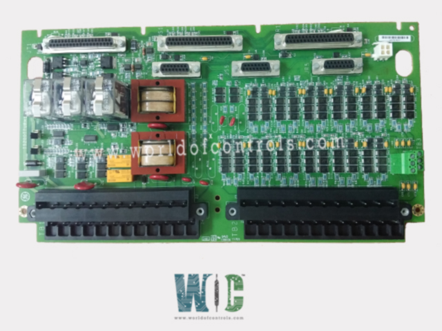
SPECIFICATIONS
Part No.: IS200TTURH1BBA
Manufacturer: General Electric
Country of Manufacture: United States of America (USA)
Number of outputs: Generator breaker coil, 5A at 125 V dc
Power supply voltage: Nominal 125 V dc to breaker coil
MPU pulse rate range: 2 Hz to 20 kHz
MPU pulse rate accuracy: 0.05 percent of reading
MPU input circuit sensitivity: 27 mV pk (detects 2 rpm speed)
Size: 33.0 cm high x 17.8 cm wide
Technology: Surface mount
Temperature Operating: -30 to 65 oC
Product Type: Terminal Board
Availability: In Stock
Series: Mark VI
Functional Description
IS200TTURH1BBA is an Terminal Board developed by GE. It is a part of Mark VI control system. The Turbine Terminal Board plays a critical role in conjunction with the PTUR turbine I/O packs as part of the Mark VIe system. It facilitates a range of inputs and outputs essential for monitoring and controlling turbine operations.
Inputs and Outputs Configuration
- The terminal board manages a diverse set of inputs and outputs, including:
- Pulse Rate Devices: 12 pulse rate devices, specifically sensing a toothed wheel to measure turbine speed accurately.
- Voltage Signals: Acquires generator voltage and bus voltage signals sourced from potential transformers, crucial for monitoring voltage parameters.
- 125 V DC Output: Provides a 125 V DC output directed to the main breaker coil, facilitating automatic generator synchronizing, a pivotal function for system operation.
- Shaft Voltage and Current Sensors: Inputs from sensors measuring induced shaft voltage and current, vital for monitoring the turbine's operational parameters.
- Overspeed Trip Signals: Facilitates three overspeed trip signals to the trip board, essential safety measures to prevent turbine overspeed conditions.
- Additional I/O Signals: Manages additional input/output signals from the trip board, enhancing system functionality.
- Relay Functions: TTURH1C is equipped with three essential relays-K25, K25P, and K25A. The closing of all three relays is necessary to provide the required 125 V DC power to engage the main breaker 52G, ensuring safe and efficient turbine operations.
Signal Distribution
- Simplex Systems: For simplex systems, signal connections to PTUR utilize the PR3 and JR4 connectors, simplifying the signal flow for efficient operations.
- TMR Systems: In Triple Modular Redundancy (TMR) configurations, signal distribution is more intricate. Signals fan out across multiple connectors - PR3, PS3, PT3, JR4, JS4, and JT4 to ensure redundancy and reliability across the system, enhancing fault tolerance in critical scenarios.
Installation
- Component Wiring to Terminal Blocks:
- Identification of Components: Pulse rate pick-ups, shaft pick-ups, potential transformers, and the breaker relay are wired to two distinct terminal blocks, TB1 and TB2.
- Terminal Blocks Specifications: Each terminal block (TB1 and TB2) is secured by two screws and comprises 24 terminals that accommodate wires up to #12 AWG.
- Shield Terminal Strip: Positioned immediately to the left of each terminal block, a shield terminal strip attached to the chassis ground ensures proper grounding.
- Jumper Configuration:
- Jumper JP1 and JP2: These jumpers facilitate the selection between simplex and TMR configurations for relay drivers K25 and K25P. Proper configuration according to system requirements is necessary for optimal functionality.
- Wire Jumper WJ1: The removal of this wire jumper (WJ1) isolates the K25A control line, directing it specifically to the TRPX board.
- Terminal Block Usage:
- TB3 for Optional TTL Connections: TB3 is designated for optional TTL connections, specifically for active speed pickups. Note that these devices require an external power supply for operation.
- Cable Connector Usage:
- Simplex Systems (PR3 and JR4): In simplex setups, cable connectors PR3 and JR4 are utilized, streamlining connections for efficient operation.
- TMR Systems (All Six Cable Connectors): In Triple Modular Redundancy (TMR) configurations, all six cable connectors are used, ensuring redundancy and enhanced fault tolerance across the system.
Generator and bus voltage sensors
- Sensor Configuration: The sensors comprise two single-phase potential transformers (PTs), each with a secondary output providing a nominal 115 V rms. Each input has a minimal loading, ensuring efficient operation with less than 3 VA of loading per input.
- Voltage Range and Synchronization: The allowable voltage range for synchronization purposes spans from 75 to 130 V rms, providing flexibility in voltage monitoring and synchronization operations.
- Isolation and Safety: Each PT input is magnetically isolated, incorporating a robust 1,500 V rms barrier to ensure electrical safety and prevent potential hazards.
- Cable Length and Compatibility: The sensors support cable lengths of up to 1,000 ft. of 18 AWG wiring, offering versatility in installation configurations and accommodating varying system layouts.
The WOC team is always available to help you with your Mark VI requirements. For more information, please contact WOC.
Frequently Asked Questions
What is IS200TTURH1BBA?
It is an Terminal Board developed by GE under the Mark VI series.
What happens if there is an issue with the solenoid relay drivers or relay contacts feedback?
Feedback discrepancies from the solenoid relay drivers or relay contacts regarding control signals result in the creation of a fault, indicating a potential problem.
How is a fault triggered in case of solenoid power loss or specific relay conditions?
Loss of power to the solenoid, along with issues involving specific relays like slow sync check relay, slow auto sync relay, slow breaker, or locked up K25 relay, initiates the creation of a fault.
What is the implication of unhealthy signals on the PTUR system?
Unhealthy signals trigger a composite diagnostic alarm referred to as L3DIAG PTUR. These diagnostic signals can be individually latched and reset using the RESET DIA signal if they return to a healthy state.
