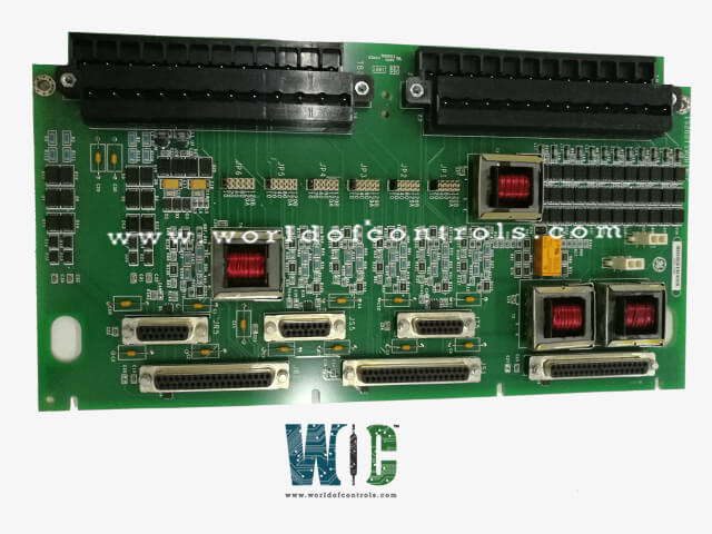
World Of Controls understands the criticality of your requirement and works towards reducing the lead time as much as possible.
IS200TSVOH1A - Servo Valve Interface Terminal Board is available in stock which ships the same day.
IS200TSVOH1A - Servo Valve Interface Terminal Board comes in UNUSED as well as REBUILT condition.
To avail our best deals for IS200TSVOH1A - Servo Valve Interface Terminal Board, contact us and we will get back to you within 24 hours.
SPECIFICATIONS:
Part Number: IS200TSVOH1A
Manufacturer: General Electric
Series: Mark VIe
Product Type: Servo Valve Interface Terminal Board
Operating System: QNX
Power Requirements: +5 V dc, 6 A
Number of input channels: 6
Number of outputs: 2
Trip Solenoid Rating: 125 V dc
Power supply voltage: 24 V dc
Voltage Range: 18 - 32 VDC
Mounting: DIN-rail mounting
Technology: Surface mount
Operating temperature: 40 to 70°C
Size: 17.8 cm high x 33.02 cm
Repair: 3-7 Day
Availability: In Stock
Country of Origin: United States
Manual: GEH-6421M
FUNCTIONAL DESCRIPTION:
IS200TSVOH1A is a Servo Valve Interface Terminal Board manufactured and designed by General Electric as part of the Mark VIe Series used in GE Distributed Turbine Control Systems. The steam/fuel valves are operated by two electro-hydraulic servo valves that are connected to the Servo Input/Output (TSVO) terminal board. LVDTs are used to measure valve position. The J5 socket on the front of VSVO and the J3 or J4 connector on the VME rack are used to connect two wires to VSVO. The JR1 connector is used by TSVO to deliver simplex signals, while the JR1, JS1, and JT1 connectors are used to fan out TMR signals. For an external trip from the protection module, use plugs JD1 or JD2.
INSTALLATION:
As shown in the figure Servo Terminal Board Wiring, directly connect the wires for the sensors and servo valves to two I/O terminal blocks on the terminal board. With 24 connections that can accommodate cabling as thick as #12 AWG, each block is secured in place with two screws. Just to the left of each terminal block is a shield termination strip connected to the chassis ground. Wires for the external trip should be connected to JD1 or JD2. Racks R, S, and T's VSVO boards should have J5 connectors connected to the front of them. In R, S, and T, connect the J1 connectors to the VME rack beneath VSVO.
OPERATION:
Four channels of bi-directional servo current outputs, LVDT position feedback, LVDT excitation, and pulse rate fluxes inputs are offered by VSVO. Up to six LVDT valve position inputs can be provided with excitation, and the TSVO will take their inputs. For each servo control loop, a choice of one, two, three, or four LVDTs is available. Applications for measuring gas turbine flow are possible with three inputs. These signals pass through TSVO and are directed to the front of the VSVO board at J5.
When de-energized, each servo output has a dedicated suicide relay that, when controlled by firmware, shorts the VSVO output signal to signal common before returning to normal operation upon a manual reset instruction. Each servo's output condition, including its voltage, current, and suicide relay, is monitored via diagnostics.
CONFIGURATION:
Jumper JP1 configures the coil current of Servo 1 in a simplex system, while jumper JP4 configures the coil current of Servo 2. For more details, see the Servo Coil Ratings table. Each servo output in a TMR system may have three coils. Servo 1's coil current is set by Jumpers JP 1 through 3, whereas Servo 2's coil current is set by Jumpers JP 4 through 6. The toolbox is where all other configuration is done.
WOC has the largest stock of OEM replacement parts for GE Distributed Control Systems. We can also repair your faulty boards and supply unused and rebuilt boards backed up with a warranty. Our team of experts is available round the clock to support your OEM needs. Our team of experts at WOC is happy to assist you with any of your automation requirements. For pricing and availability on parts and repairs, kindly contact our team by phone or email.
What is a Servo Valve Interface Terminal Board?
A Servo Valve Interface Terminal Board is a component used in hydraulic and pneumatic systems to provide connections between the servo valve and the control electronics. It typically includes terminals for wiring and may include features for signal conditioning or protection.
What kind of signals does the Servo Valve Interface Terminal Board handle?
The board typically handles both analog and digital signals, including input signals from the control system and feedback signals from the servo valves, such as position feedback.
What are the diagnostic features of the Servo Valve Interface Terminal Board?
The board includes diagnostic features that monitor the health and performance of the servo valves and the communication between the board and the valves. It can detect faults such as signal loss, incorrect positioning, and power failures.