SPECIFICATIONS
Part No.: IS200TRTDH2D
Manufacturer: General Electric
Country of Manufacture: United States of America (USA)
Size: 17.8 cm wide x 33.02 cm high
Temperature: -30 to + 65oC
Span: 0.3532 to 4.054 V
Max lead resistance: 15 ohm
Technology: Surface-mount
Number of relay channels 12 relays
Product Type: Resistance Temperature Device Terminal Board
Availability: In Stock
Series: Mark VIe
Functional Description
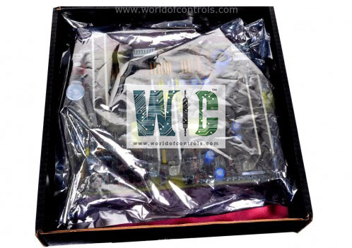
IS200TRTDH2D is a Resistance Temperature Device Terminal Board developed by GE. It is a part of Mark VIe control system. The TRTD terminal board is designed to accommodate 16 three-wire RTD inputs. These inputs are connected through two barrier-type terminal blocks, ensuring a secure and organized wiring arrangement. To enhance reliability and performance, the terminal board is equipped with noise suppression circuitry. This feature is crucial for protecting the system against electrical surges and high-frequency noise, which can otherwise compromise the accuracy of temperature measurements.
Installation
- The installation process for the board involves directly wiring the sixteen RTDs to two dedicated terminal blocks mounted on the terminal board. These terminal blocks are designed to securely hold and connect the RTD wires, ensuring reliable performance and ease of maintenance.
- Each terminal block is firmly secured to the terminal board with two screws, providing stability and ensuring a robust connection. The terminal blocks feature 24 terminals each, which are capable of accepting wires up to 12 AWG (American Wire Gauge). This allows for a versatile range of wire sizes to be used, accommodating various installation requirements and ensuring compatibility with different RTD configurations.
- Adjacent to each terminal block, there is a shield terminal strip that is connected to the chassis ground. This strip is located immediately to the left of each terminal block, facilitating easy grounding of the RTD shields. Proper grounding is essential for minimizing electrical noise and interference, thereby enhancing the accuracy and reliability of the temperature measurements.
Operation
- The TRTD (Resistance Temperature Device) terminal board operates by supplying a 10 mA direct current (dc) multiplexed excitation current to each RTD. This current is not continuous but is applied in a multiplexed manner. The RTDs can be either grounded or ungrounded, providing installation flexibility. The terminal board is capable of supporting RTDs located up to 300 meters (984 feet) away from the turbine control cabinet, with a maximum allowable two-way cable resistance of 15 ohms.
- The I/O processor board contains an analog-to-digital (A/D) converter that samples each signal and the excitation current. Sampling occurs four times per second in normal mode scanning and 25 times per second in fast mode scanning. The sampling interval is synchronized with the power system frequency to ensure accuracy.
- The I/O processor software performs linearization for the selection of 15 different RTD types. This software-based linearization ensures precise temperature measurements across a variety of RTD types. The system also detects open and short circuits in the RTDs by identifying out-of-range values. If an RTD is found to be outside hardware limits, it is automatically removed from the scanned inputs to prevent any adverse effects on other input channels. A repaired RTD channel is reinstated automatically after 20 seconds, or it can be manually reinstated if necessary.
- All RTD signals undergo high-frequency decoupling to ground upon entry, which helps in reducing noise and protecting the integrity of the signal. RTD multiplexing on the I/O processor is coordinated by redundant pacemakers. This redundancy ensures that the loss of a single cable or I/O processor does not result in the loss of any RTD signals in the control database. The redundancy provides a robust and reliable means of maintaining continuous and accurate temperature monitoring, even in the event of component failures.
Fault Detection
- High/Low (Hardware) Limit Check: This involves monitoring the hardware components to ensure they operate within predefined high and low limits. If any component exceeds these limits, the system flags it as a potential fault, which could indicate issues like overheating, overvoltage, or undervoltage.
- High/Low (Software) System Limit Check: This type of fault detection checks the software parameters and system operations against set high and low thresholds. If the software operations or system parameters fall outside these limits, it triggers an alert. This helps in identifying problems such as software bugs, data corruption, or unexpected operational conditions.
- Failed ID Chip: The system continuously verifies the integrity and functionality of the identification (ID) chip. If the ID chip fails, it could indicate a serious fault, as this chip is crucial for system identification, authentication, and proper functioning. A failed ID chip might prevent the system from recognizing or validating hardware components correctly, leading to operational issues.
The WOC team is always available to help you with your Mark VI requirements. For more information, please contact WOC.
Frequently Asked Questions
What is IS200TRTDH2D?
It is a resistance temperature device terminal board developed by GE under the Mark VIe series.
How many RTD inputs can the terminal board accommodate?
The terminal board can accommodate 16 three-wire RTD inputs.
What type of terminal blocks are used for connecting the RTDs?
The RTDs are connected using two barrier-type terminal blocks, each secured with two screws and featuring 24 terminals.
What is the maximum wire size that the terminal blocks can accept?
The terminal blocks can accept wires up to 12 AWG (American Wire Gauge).
Is there any noise suppression circuitry on the terminal board?
Yes, the terminal board is equipped with noise suppression circuitry to protect against electrical surges and high-frequency noise.
