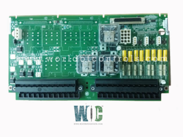
SPECIFICATIONS
Part No.: IS200TRPGH2BCC
Manufacturer: General Electric
Country of Manufacture: United States of America (USA)
Current suppression: MOV on TREG
Flame detectors: 8 detectors per TRPG
Temperature: -30 to 65 oC
Product Type: Primary Trip terminal board
Availability: In Stock
Series: Mark VIe
Functional Description
IS200TRPGH2BCC is a primary trip terminal board developed by GE. It is part of the Mark VIe control system. It is governed by the primary turbine protection controller, which can either be a VTUR or PTUR. These controllers are integral to the turbine protection system, ensuring that any anomalies or unsafe conditions are promptly addressed to prevent damage to the turbine and associated equipment.
Features
- The terminal board is designed with nine magnetic relays organized into three distinct voting circuits. This arrangement is critical for interfacing with three-trip solenoids known as ETDs. The voting circuits add an extra layer of reliability and safety, as they require a consensus among the relays to trigger a trip, thus minimizing the chances of false trips caused by single-point failures.
- The terminal board works in tandem with the TREG terminal board. Together, they form the primary and emergency sides of the interface to the ETDs. This dual setup ensures that the turbine can be safely shut down in both standard operating conditions and emergency situations. The primary side (TRPG) handles regular trip signals, while the emergency side (TREG) is designed to take over if the primary system fails, providing an additional safeguard.
- An aspect of the board is its ability to accommodate inputs from up to eight Geiger-Mueller flame detectors. These detectors are vital for gas turbine applications, as they monitor the presence and stability of the flame within the turbine. If the flame is extinguished or becomes unstable, the flame detectors send signals to the TRPG, which can then initiate a trip to shut down the turbine and prevent potential hazards, such as unburned fuel accumulation or turbine damage.
Installation
- Proper installation of the terminal board is crucial for ensuring the reliability and safety of gas turbine operations. Follow these detailed steps to install and connect the necessary components correctly.
- Start by identifying the first I/O (input/output) terminal block on the TRPG terminal board and connecting the wires for the three trip solenoids directly to this block, ensuring secure connections to prevent operational failures or false trips. Next, locate the second terminal block, designated for flame detectors, and connect their wires if flame detectors are being used. Each detector should have a designated terminal to ensure accurate signal transmission.
- For supplying power to the flame detectors, connect their power supply wires to the J3, J4, and J5 plugs on the TRPG terminal board, making sure the connections are secure and the correct voltage is supplied to avoid damage. Similarly, locate the J1 plug for the trip solenoids’ power supply and connect the 125 V DC power supply wires, verifying voltage and polarity before connecting to prevent electrical faults.
- Finally, identify the J2 plug used for transferring power to the TREG board and connect the appropriate power transfer wires, ensuring the board receives the necessary power to function correctly. After all connections are made, double-check each one for security and accuracy, perform a continuity test on all connected wires, and power on the system to monitor the operation of the trip solenoids and flame detectors, verifying correct signal reception and processing by the terminal board.
- Ensure all power sources are off before starting the installation to avoid electrical hazards, follow the manufacturer’s guidelines for wire sizes, power ratings, and connection procedures, and seek assistance from a qualified technician if you are not experienced with electrical installations. Following these steps ensures the terminal board and its components are installed correctly, contributing to the safe and efficient operation of your gas turbine system.
The WOC team is always available to help you with your Mark VIe requirements. For more information, please contact WOC.
Frequently Asked Questions
What is IS200TRPGH2BCC?
It is a primary trip terminal board developed by GE under the Mark VIe series.
What diagnostics does the I/O board perform on the terminal board?
The I/O board runs comprehensive diagnostics on the terminal board, which includes monitoring feedback from the trip solenoid relay driver and contact, the solenoid power bus, and the flame detector excitation voltage to ensure it is within acceptable limits.
What happens if a diagnostic signal goes beyond limits?
If any diagnostic signal, such as those from the trip solenoid relay driver, solenoid power bus, or flame detector excitation voltage, goes beyond acceptable limits (either too low or too high), a diagnostic alarm is created to alert the operators of the issue.
What is the role of connectors JR1, JS1, and JT1 on the terminal board?
Connectors JR1, JS1, and JT1 on the terminal board each have their ID device, which contains critical information such as the terminal board's serial number, board type, revision number, and plug location.
