SPECIFICATIONS
Part No.: IS200TRPAH2R
Manufacturer: General Electric
Country of Manufacture: United States of America (USA)
Input channels: 18 dynamic pressure inputs
Output channels: 18 buffered outputs
Gain adjustment options: 1x, 2x, 4x, and 8x
Temperature: -30 to 65 oC
Product Type: Primary Trip Terminal Board
Availability: In Stock
Series: Mark VIe
Functional Description
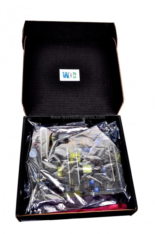
IS200TRPAH2R is a Primary Trip Terminal Board developed by GE. It is a part of Mark VIe control system. The Turbine Primary Trip Terminal Board works in conjunction with PTUR turbine I/O packs or the TTUR terminal board, providing critical monitoring and control functions for turbine trip mechanisms. This ensures the safe and reliable operation of turbines. Below is an expanded description of its inputs, outputs, and overall functionality.
Features
- The board supports up to 12 passive pulse rate devices, which are distributed across three sections (R, S, T), with four devices per section. These passive devices do not require an external power supply; they function by sensing the teeth of a toothed wheel, allowing for precise measurement of the turbine's rotational speed.
- In addition, the board can accommodate six active pulse rate inputs, with two inputs allocated per TMR (Triple Modular Redundancy) section. Unlike passive devices, active pulse rate inputs are powered sensors that actively generate signals in response to the movement of the toothed wheel, ensuring high accuracy in speed measurement.
- The board features two TMR voted output contacts, which are crucial for the turbine's safety mechanisms. These contacts control the main breaker coil, responsible for tripping the turbine when necessary. They are designed to operate at either 24 V DC (H1) or 125 V DC (H2), providing flexibility and compatibility with different control voltages.
- There are four voltage detection circuits on the TRPAH1A board. These circuits are designed to monitor the trip string voltage, ensuring that the trip signals are correctly received and processed. They can handle voltages ranging from 24 to 125 V DC, making them versatile for various applications.
- The board also includes a single ‘Fail-safe’ Emergency Stop (ESTOP) input. This input operates at 24-125 V DC and is used to remove power from the trip relays, providing a fail-safe mechanism to immediately stop the turbine in emergency situations.
- For systems utilizing Triple Modular Redundancy (TMR), the TRPAH1A board ensures redundancy and reliability by distributing signals to the PR3, PS3, PT3, JR4, JS4, and JT4 connectors. These connectors handle the primary and secondary trip signals for each of the three TMR sections, ensuring robust signal processing and redundancy.
Installation
- Wiring Connections to TB1: TTL pulse rate pickups, voltage detection circuits, the E-STOP input, and the breaker relay are all wired to the I/O terminal block labeled TB1. This terminal block includes connections for TTL pulse rate pickups used for speed measurement, voltage detection circuits for monitoring voltage levels in the trip string, the Emergency Stop (E-STOP) input for immediate turbine shutdown, and breaker relay connections to control the tripping mechanism of the turbine.
- Wiring Connections to TB2: Passive pulse rate pickups are wired to the terminal block labeled TB2. These sensors, which do not require an external power supply, generate signals based on the movement of a toothed wheel. This separation ensures organized wiring and appropriate routing of each type of input.
- Terminal Block Specifications: Each terminal block, TB1 and TB2, is held down with two screws to ensure stability and reliable connections. Both blocks have 24 terminals, allowing for multiple connections, and can accept wires up to 12 AWG, which provides sufficient capacity for industrial wiring needs. This capacity ensures robust and secure connections for all necessary wiring in industrial applications.
- Shield Termination: A shield termination strip is attached to the chassis ground and located immediately to the left of each terminal block. This strip is used to ground the shields of the connected wires, which helps minimize electrical noise and interference. Proper grounding is essential for maintaining signal integrity and ensuring accurate measurements and controls.
- Configuring Speed Input Connections: The board must be configured for the desired speed input connections using jumpers JP1 and JP2. These jumpers control the fanning out of pulse rate pickup signals from the R section to the S and T PTURs. Correctly setting these jumpers is crucial for ensuring that the speed inputs are properly routed and processed by the system.
The WOC team is always available to help you with your Mark VIe requirements. For more information, please contact WOC.
Frequently Asked Questions
What is IS200TRPAH2R?
It is a Primary Trip Terminal Board developed by GE under the Mark VIe series.
How should I wire the components to the board?
TTL pulse rate pickups, voltage detection circuits, E-STOP input, and the breaker relay should be wired to terminal block TB1. Passive pulse rate pickups should be connected to TB2.
What wire size can I use with the TB1 and TB2 terminal blocks?
Both TB1 and TB2 terminal blocks can accept wires up to 12 AWG.
Why is grounding important in the installation of the terminal board?
Proper grounding, facilitated by the shield termination strip attached to chassis ground next to each terminal block, helps minimize electrical noise and interference, ensuring accurate measurements and controls.
