World Of Controls understands the criticality of your requirement and works towards reducing the lead time as much as possible.
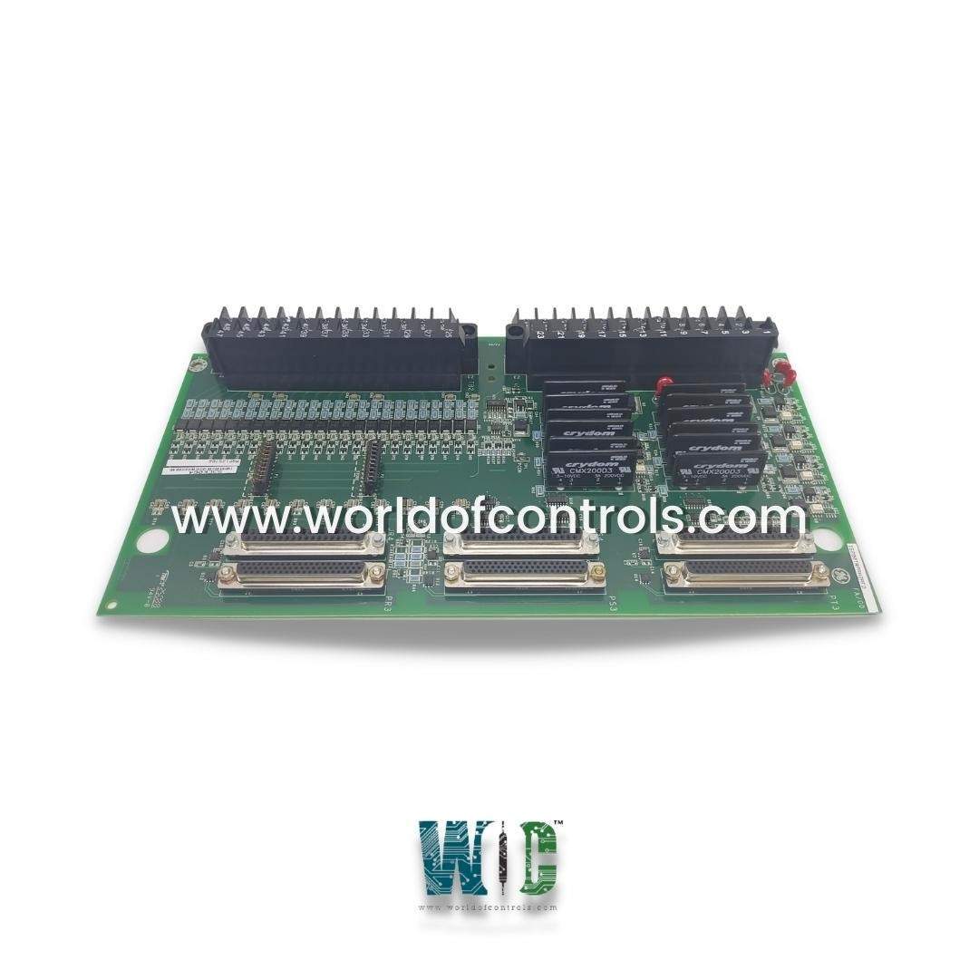
IS200TRPAH2AGD - Aeroderivative Turbine Primary Trip Terminal Board is available in stock which ships the same day.
IS200TRPAH2AGD - Aeroderivative Turbine Primary Trip Terminal Board comes in UNUSED as well as REBUILT condition.
To avail our best deals for IS200TRPAH2AGD - Aeroderivative Turbine Primary Trip Terminal Board, contact us and we will get back to you within 24 hours.
SPECIFICATIONS:
Part Number: IS200TRPAH2AGD
Manufacturer: General Electric
Series: Mark VIe
Board Type: Aeroderivative Turbine Primary Trip Terminal Board
Number of inputs: 3x4
Number of outputs: 2 trip
Input span, transmitters: 1-5 V dc
Maximum lead Resistance: 15 maximum
MPU pulse rate range: 2 Hz to 20 kHz
MPU input circuit sensitivity: 27 mV
Dimensions: 33.0 cm wide x 17.08 cm high
Mounting Type: Surface-mount
Operating Temperature Range: 30°C to +65°C
Repair: 3-7 Days
Availability: In Stock
Country of Origin: United States
Manual: GEH-6721D
FUNCTIONAL DESCRIPTION:
IS200TRPAH2AGD is an Aeroderivative Turbine Primary Trip Terminal Board manufactured and designed by General Electric as part of the Mark VIe Series used in GE Distribution Turbine Control Systems. It works with PTUR / YTUR I/O packs and TTUR terminal boards as part of the Mark VIe control system. The inputs and outputs are as follows:
Twelve passive pulse rate devices (four per R/S/T section) sensing a toothed wheel to measure the turbine speed. Or six active pulse rate inputs (two per TMR section)
Two 24 V dc (H1A) or 125 V dc (H2A) TMR voted output contacts to the main breaker coil for trip coil.
Four 24-125 V dc voltage detection circuits for monitoring trip string.
One 24-125 V dc ‘Fail-safe’ ESTOP input for removing power from trip relays. For TMR systems, signals fan out to the PR3, PS3, PT3, JR4, JS4, and JT4 connectors.
INSTALLATION:
TTL pulse rate pick-ups, voltage detection, E-Stop, and the breaker relay are wired to the I/O terminal blocks TB1. Passive pulse rate pickups are wired to TB2. Each block is held down with two screws and has 24 terminals accepting up to #12 AWG wires. A shield termination strip attached to the chassis ground is located immediately to the left of each terminal block. The TRPA must be configured for the desired speed input connections using the following table. Jumpers JP1 and JP2 select fanning of the R section pulse rate pickups to the S and T PTURs or YTURs
DIAGNOSTICS:
OPERATION:
System Design: The TRPA board is designed for application in two different ways. When a TTUR terminal board is used to hold three PTUR I/O packs, the TRPA terminal board may be connected using three cables with DC-37 pin connectors on each end. In this mode of operation, the TRPA provides two contact-voted trip relay outputs, ESTOP, and four voltage sensors. TTUR provides the normal set of features described for that board.
Voltage Monitors: The trip relays on TRPA may be freely located anywhere in a trip string. Because the trip string circuit is not fixed, there are four general-purpose isolated voltage sensor inputs on TRPA. These may be used to monitor any points in the trip system and drive the voltage status into the system controller where action may be taken. Typical use of these inputs may be to sense the power supply voltage for the two trip strings and to sense the solenoid voltage of the device being driven by the relays. This set of applications is used in the wording of the board symbol, but the sensors may be freely applied to best serve the application.
Trip Relays: The trip relays are made using sets of six individual form A devices arranged in a voting pattern. Any two controllers that vote to close will establish a conduction path through the set. Because detection of a shorted relay is important to preserve tripping reliability there is a sensing circuit applied to each of the sets of relays.
WOC has the largest stock of OEM Replacement Parts for GE Distribution Control Systems. We can also repair your faulty boards and supply unused and rebuilt boards backed up with a warranty. Our team of experts is available around the clock to support your OEM needs. Our team of experts at WOC is happy to assist you with any of your automation requirements. For pricing and availability on parts and repairs, kindly contact our team by phone or email.
What is the function of the Primary Trip Terminal Board?
The Primary Trip Terminal Board is responsible for processing trip signals and initiating turbine shutdown in case of faults. It receives inputs from protection devices like overspeed sensors, pressure switches, and fire detection systems. When a hazardous condition is detected, it triggers relays to cut off the fuel supply and stop the turbine.
How does the trip terminal board process trip signals?
The trip terminal board receives signals from various protection mechanisms and processes them through relays and logic circuits. If a trip condition is met, it de-energizes the trip relay, activating the shutdown process. This ensures a fast and reliable response to potential turbine failures.
What are the key electrical specifications of the trip terminal board?
Most trip terminal boards operate on 24V DC or 120V AC input voltage and use dry contact or solid-state relays. The response time is typically less than 10 milliseconds to ensure immediate shutdown. It is designed with high dielectric strength to withstand voltage fluctuations and harsh environments.