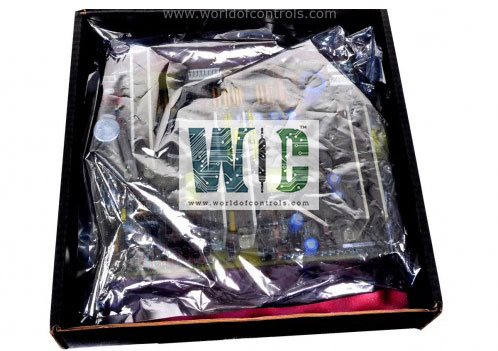
SPECIFICATIONS
Part No.: IS200TRLYH2EAA
Manufacturer: General Electric
Country of Manufacture: United States of America (USA)
Size: 17.8 cm wide x 33.02 cm high
Temperature: -30 to + 65oC
Dry circuit relays: 12
Relay Type: Solid-State Form A
Relay suppression: No
Solenoid relay sensing: No
Operating voltage V dc: 28 V
Internal switching power supply: No
Technology Surface-mount
Product Type: Solid-State Relay Output
Availability: In Stock
Series: Mark VIe
Functional Description
IS200TRLYH2EAA is a solid-state relay output developed by GE. It is a part of Mark VIe control system. The board comprises 12 output circuits, utilizing solid-state relays for enhanced reliability and performance. Each circuit is equipped with isolated output voltage feedback, providing accurate monitoring and control capabilities. Relay drivers, fuses, and jumpers are installed on the relay terminal board. For simplex operation, D-type connectors, through JA1, transmit control signals and monitor feedback voltages between the I/O processors and TRLY.
Features
- Certification for Hazardous Environments: The use of solid-state relays enables the board to be certified for Class 1 Division 2 applications, ensuring compliance with stringent safety regulations and standards in hazardous environments.
- Specifically designed for 24 V DC applications, it offers compatibility with a wide range of industrial setups.
Output Configuration: Unlike traditional mechanical relay boards that often feature form-C contacts, the board offers single, normally open contacts for all 12 outputs. This configuration enhances simplicity and reliability in control operations.
- Solenoid Power Distribution: It's important to note that the board does not include user solenoid power distribution. This allows for greater flexibility in power management and configuration, depending on the specific requirements of the application.
- By leveraging solid-state relay technology and providing isolated output voltage feedback, the board offers precise control and safety features, making it an ideal choice for demanding industrial environments, particularly those with hazardous conditions.
Contact Voltage Feedback
- Isolated Voltage Sensing: The board integrates isolated feedback voltage sensing, establishing a connection to the relay outputs. This enables precise observation of the voltage across each relay output circuit while maintaining isolation from the control circuitry.
- Each relay is equipped with a dedicated contact sensing circuit, ensuring accurate voltage feedback for monitoring purposes.
- Similarity to TRLYH1C: This feature resembles the voltage sensing capability, albeit with simpler hardware implementation. It provides similar functionality with reduced complexity, enhancing reliability and ease of maintenance.
- Leakage Current Management: The voltage sensing circuit allows a small leakage current to flow, facilitating the operation of the isolated circuitry. Typically, the leakage current comprises the sum of the current passing through the turned-off solid-state relay and the current drawn by the voltage sensing circuit.
Configuration
- Jumpers (JP1 through JP12): If contact voltage sensing is necessary, carefully insert jumpers into the designated jumper slots corresponding to the selected relays. This enables the board to sense contact voltage accurately, facilitating proper relay functionality.
- Fuses (FU1 through FU12): For relays requiring power (1-6), it's imperative to ensure adequate power supply by placing two fuses in each power circuit associated with those relays. For instance, both FU1 and FU7 should be inserted to supply power to relay output 1, ensuring reliable operation.
Operation
- Relay Terminal Board Components: The relay terminal board hosts relay drivers, fuses, and jumpers, crucial for its operation. These components collectively enable the board to manage relay activation and ensure proper electrical protection.
- Simplex Operation: For simplex operation, control signals and monitor feedback voltages are transmitted between the I/O processors and the TRLY (relay terminal board) via D-type connectors, specifically through connector JA1. This setup facilitates seamless communication and coordination between system components.
- Relay Characteristics: Relays on the terminal board are driven at the frame rate and possess a robust 3.0 A rating. These relays are designed to withstand rigorous operational conditions, offering high reliability and performance.
- Voltage Ratings: The relays exhibit specific voltage ratings to ensure safe and efficient operation. The rated contact-to-contact voltage is 500 V AC for one minute, while the rated coil-to-contact voltage is 1,500 V AC for one minute. These ratings ensure compliance with safety standards and guarantee reliable performance under various conditions.
- Operational Parameters: Relays on the board feature a typical time to operate of 10 ms, ensuring swift response and efficient relay switching. Additionally, relays 1-6 are equipped with a 250 V MOV (Metal Oxide Varistor) for transient suppression between normally open and power return terminals. This feature enhances the reliability of the relays by mitigating the effects of transient voltage spikes.
The WOC team is always available to help you with your Mark VIe requirements. For more information, please contact WOC.
Frequently Asked Questions
What is IS200TRLYH2EAA?
It is a solid-state relay output developed by GE under the Mark VIe series.
What happens during power-up?
Relays stay de-energized to ensure safe operation.
What failsafe features are present?
If a cable is unplugged or communication with the I/O processor is lost, relays de-energize automatically.
How does it handle AC applications?
In AC applications, the board utilizes a load control device that switches off at a current zero crossing. This ensures that no inductive energy is present in the load at turn-off time, enhancing safety and efficiency.
What basic protection is provided for the AC relay?
It incorporates a metal oxide varistor (MOV) with a clamp voltage coordinated with the relay voltage rating. This serves as a basic protection mechanism against voltage spikes and transients.
