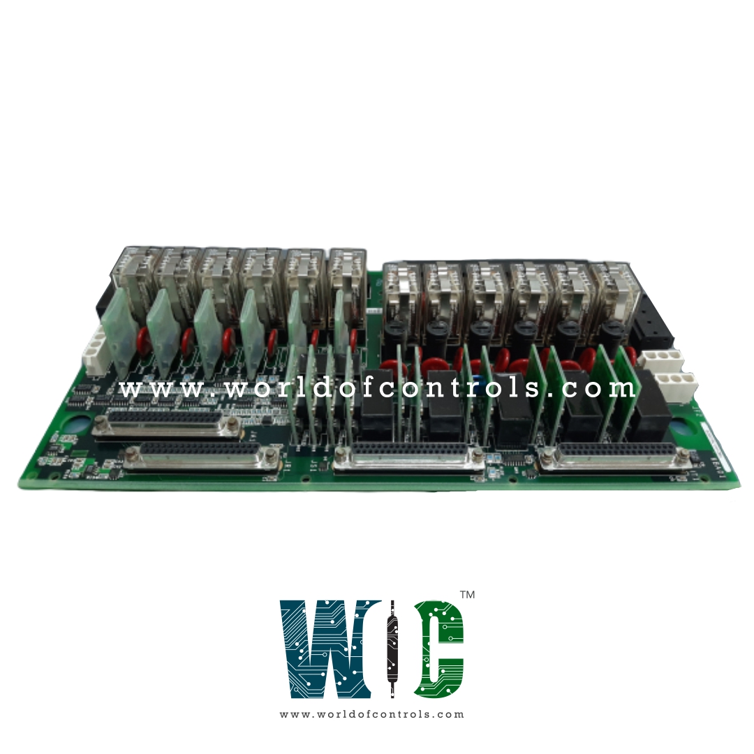
World Of Controls understands the criticality of your requirement and works towards reducing the lead time as much as possible.
IS200TRLYH1DAC - Simplex Contact Output Terminal Board is available in stock which ships the same day.
IS200TRLYH1DAC - Simplex Contact Output Terminal Board comes in UNUSED as well as REBUILT condition.
To avail our best deals for IS200TRLYH1DAC - Simplex Contact Output Terminal Board, contact us and we will get back to you within 24 hours.
SPECIFICATIONS:
Part Number: IS200TRLYH1DAC
Manufacturer: General Electric
Series: Mark VIe
Function: Simplex Contact Output Terminal Board
Number of relay channels: 12
Rated voltage on relays: 125 V dc
Dimensions: 17.8 cm wide x 33.02 cm high
Operating Temperature: -30 to + 65 °C
Controller and I/O module Redundancy: Simplex
Internal operating system: QNX
Power Consumption: 4 W
Analog outputs: 0 to 10 V
Configuration Software: ToolboxST
Country of Manufacture: United States (USA)
Availability: In Stock
Manual: GEH-6421M
FUNCTIONAL DESCRIPTION:
IS200TRLYH1DAC is a Simplex Contact Output Terminal Board manufactured and designed by General Electric as part of the Mark VIe Series used in GE Distributed Control Systems. The TRLYH1D terminal board features 12 plug-in magnetic relays. The first six relays can be configured with jumpers for either dry Form-C contact outputs or for controlling external solenoids. Field solenoid power can be supplied by a standard 125 V DC or 115/230 V AC source, or optionally, a 24 V DC source with jumper-selectable fuses and integrated suppression. The next five relays (7-11) provide unpowered isolated Form-C contacts, while Relay 12 is also an isolated Form-C contact designated for specific uses, such as ignition transformers. In Mark VIe systems, the TRLY board is operated by the VCCC or VCRC board, with molded-plug cables connecting the terminal board to the VME rack housing the I/O boards. Both Simplex and TMR configurations are supported, with plug JA1 used in Simplex systems, and JR1, JS1, and JT1 plugs used in TMR systems.
INSTALLATION:
The 12 relay outputs connect directly to two I/O terminal blocks installed on the terminal board, as illustrated in the accompanying figure. Each block is secured with two screws and features 24 terminals that accommodate wires up to #12 AWG.
A shield terminal strip, grounded to the chassis, is located on the left side of each terminal block. Typically, solenoid power for outputs 1-6 connects via JF1, while JF2 enables power daisy-chaining to additional TRLY boards. Alternatively, when JF1/JF2 is not in use, customer-supplied power can be connected directly to TB3. JG1 supplies power to the customer’s designated solenoid for Output 12.
OPERATION:
WOC has the largest stock of OEM replacement parts for GE Distributed Turbine Control Systems. We can also repair your faulty boards and supply unused and rebuilt boards backed up with a warranty. Our team of experts is available round the clock to support your OEM needs. Our team of experts at WOC is happy to assist you with any of your automation requirements. For pricing and availability on parts and repairs, kindly contact our team by phone or email.
What is a Simplex Contact Output Terminal Board?
A Simplex Contact Output Terminal Board is designed for single-channel control applications, providing reliable output contacts to control various devices and systems.
How many output contacts does the terminal board support?
The terminal board typically supports a specified number of output contacts (e.g., 12 or 16), depending on the model.
What types of output contacts are available?
The outputs are usually Form-C (SPDT) contacts, which can be configured for various applications, including controlling relays, solenoids, or other electronic devices.
What are the voltage and current ratings for the contacts?
Output contacts typically have a voltage rating of up to 250 V AC or DC and a current rating of up to 10 A, depending on the specific board design.