World Of Controls understands the criticality of your requirement and works towards reducing the lead time as much as possible.
IS200TREGS1B - Turbine Emergency Trip Board is available in stock which ships the same day.
IS200TREGS1B - Turbine Emergency Trip Board comes in UNUSED as well as REBUILT condition.
To avail our best deals for IS200TREGS1B - Turbine Emergency Trip Board, contact us and we will get back to you within 24 hours.
SPECIFICATIONS
Part Number: IS200TREGS1B
Manufacturer: General Electric
Series: Mark VI
Product Type: Emergency Turbine Board
Number of Trip Solenoids: 3
Country/Region of Manufacture: United States
Availability: In Stock
Manual: GEH-6421J
FUNCTIONAL DESCRIPTION
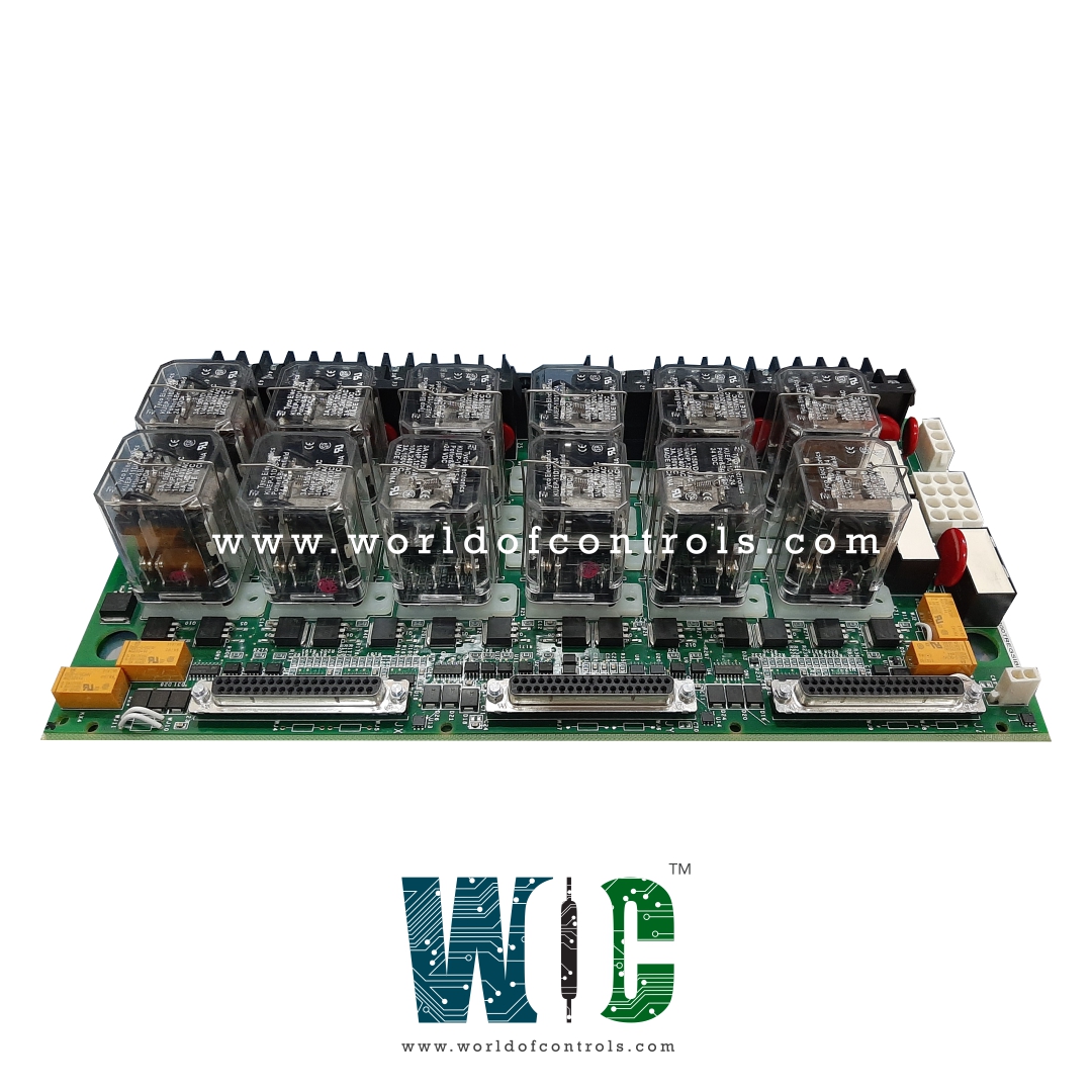
IS200TREGS1B is a Turbine Emergency Trip Board manufactured by General Electric as part of the Mark VI Series used in gas turbine control systems. Three emergency trip solenoids are powered by TREG, which is managed by the I/O controller. The TREG and TRPG terminal boards can be wired together to accommodate up to three trip solenoids. TRPG supplies the negative side of the solenoids' dc power, whereas TREG supplies the positive side. The TREG's 12 relays, nine of which form three groups of three to vote inputs controlling the three trip solenoids, are controlled by the I/O controller, which also performs emergency Overspeed protection and emergency stop operations. There are various board types, including the following:

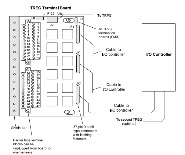
Fig 1: TREG Turbine Emergency Trip Terminal Board, and I/O Controller
Typically, one H3B and one H4B board are used in tandem in redundant TREG applications. To preserve the control power separation built into these systems, system repairs must be carried out using the appropriate type of board. The TPRO interfaces with the TREG terminal board in Mark VI systems. TREG and the TPRO module are connected by cables with molded plugs.
INSTALLATION:
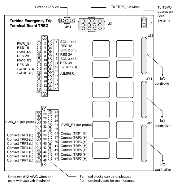
The first I/O terminal block is directly wired to the three trip solenoids, the economizing resistors, and the emergency stop. The second terminal block can accept wiring for up to seven trip interlocks. The following figure displays the wiring connections.

Fig 2: TREG Terminal Board Wiring
The J2 power cable and the trip solenoids are the only connections to the control modules since the I/O controller controls all aspects of TREG. When a turbine trips in simplex systems, a third cable transmits a trip signal from J1 to the TSVO terminal board, which operates a servo valve clamp.
CONTROL OF TRIP SOLENOIDS:
Both TRPG and TREG operate the trip solenoids so that either one can cut the electricity and open the fuel or steam valves by activating the hydraulics. The I/O controller provides 28 V dc to the nine trip relay coils on TREG. The trip solenoids draw up to 1 A with a 0.1 second L/R time constant and are powered by 125 V dc through socket J2.
The solenoids, which energize in run mode and de-energize in trip mode, are fed by an independently fused 125 V dc feeder from the turbine control. Each 125 V dc feeder from the power distribution module is monitored by diagnostics at its point of entry on the terminal board to check the integrity of the fuse and the cable connection.

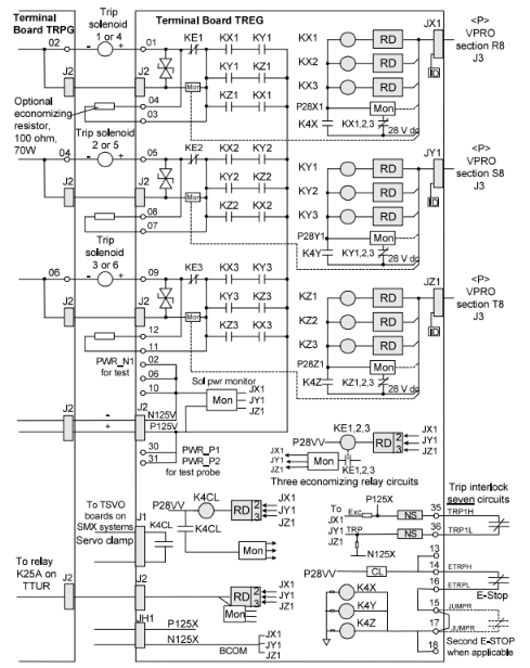
Fig 3: TREG Board, Trip Interlocks, and Trip Solenoids
For each solenoid, the positive 125 V dc feeder is connected to two series connections from each emergency trip relay (ETR1, 2, 3), while the negative 125 V dc feeder is connected to two series contacts from each principal trip relay (PTR1, 2, 3 in TRPG). For each solenoid, an economizing relay (KE1, 2, 3) with a typically closed contact is provided in parallel with the current-limiting resistor. After the solenoids are energized, these relays are utilized to lower the current load. The I/O controller's 28 V dc supply powers the ETR and KE relay coils. In the R8, S8, and T8 portions, each I/O controller provides a separate 28 V dc source.
An external manual emergency trip contact denoted as E-STOP is powered by the 28 V dc bus, which is currently limited. In the event of a manual emergency trip, the 28 V dc bus is severed from the ETR and KE relay coils by three master trip relays (K4X, K4Y, and K4Z). Any trip that starts in the protection module (like EOS) or the TREG (like a manual trip), or both, will cause each of the three protection module sections to send a trip command over the IONet to the control module, and this trip command can be used to determine where the trip originated.
DIAGNOSTICS:
The TREG board and linked devices are subjected to diagnostic tests by the I/O controller. The diagnostics cover the solenoid voltage source, the trip relay driver and contact feedbacks, the economizer relay driver and contact feedbacks, the K25A relay driver and coil, the servo clamp relay driver, and contact feedback, and the economizer relay driver and contact feedbacks. A fault is produced if even one of these deviates from the desired value.
The I/O controller queries the ID devices on the TREG connections JX1, JY1, and JZ1. The terminal board serial number, board type, revision number, and plug location are all encoded on the read-only ID device chip. A hardware incompatibility fault is produced when a mismatch is found while reading the chip by the I/O board.
WOC has the largest stock of GE Speedtronic Mark VI Replacement Parts. We can also repair your faulty boards. WORLD OF CONTROLS can also supply unused and rebuilt backed up with a warranty. Our team of experts is available round the clock to support your OEM needs. Our team of experts at WOC is happy to assist you with any of your automation requirements. For pricing and availability on any parts and repairs, kindly get in touch with our team by phone or email.
What is IS200TREGS1B?
The IS200TREGS1B is an emergency trip termination board under Mark VI series developed by General Electric.
How many relays does IS200TREGS1B have?
Twelve contactors, also known as relays, are grouped in two rows of six on this circuit board.
How to obtain IS200TREGS1B part?
Contact WOC for IS200TREGS1B or any other turbine control requirements.