SPECIFICATIONS
Part No.: IS200TREGH4B
Manufacturer: General Electric
Series: Mark VI
Technology: Surface mount
Trip interlock isolation: Optical isolation to 1500 V
Trip interlock filter: Hardware filter, 4 ms
Availability: In Stock
Country of Manufacture: United States (USA)
Functional Description
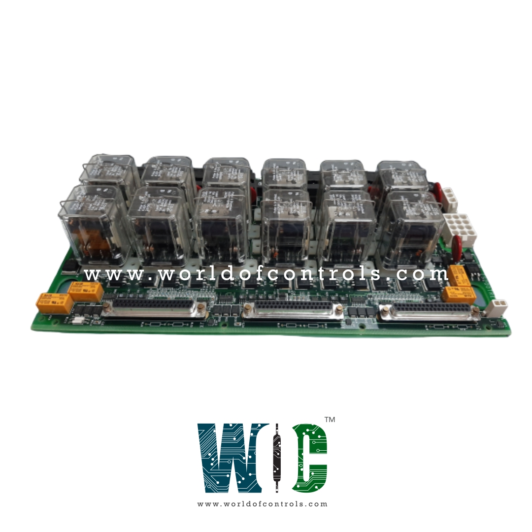
IS200TREGH4B is an Turbine Turbine Emergency Trip Terminal Board developed by GE. It is a part of Mark VI control system. The Gas Turbine Emergency Trip (TREG) terminal board is a critical component in gas turbine systems, responsible for providing power to three emergency trip solenoids. These solenoids play a crucial role in emergency overspeed protection and emergency stop functions. The TREG board is under the control of the I/O controller, which manages its twelve relays, nine of which are grouped into three sets of three to vote inputs and control the three trip solenoids.
Operation
- The TREG terminal board plays a vital role in the gas turbine system, where it is entirely controlled by the VPRO protection module. The only connections to the control modules are the J2 power cable and through the trip solenoids. In simplex systems, a third cable carries a trip signal from J1 to the TSVO terminal board, providing a servo valve clamp function upon turbine trip.
- Online tests enable the system operator to manually trip each of the trip solenoids individually. These tests can be initiated either through the PTR (Primary Trip Relay) relays from the controller or through the ETR (Emergency Trip Relay) relays from the protection module. The software allows for precise control and monitoring of these tests, providing real-time feedback and status updates.
- To ensure accurate feedback during the online tests, a contact from each solenoid circuit is wired back to the controller as a contact input. This contact input serves as a positive indication that the solenoid has successfully tripped. This feature adds an extra layer of assurance that the trip solenoids are operating as intended.
- In addition to online tests, the application software offers primary and emergency offline overspeed tests. These tests are designed to verify the actual trips resulting from software simulated trip overspeed conditions. By simulating overspeed conditions, the software can effectively assess the response of the trip solenoids and validate their ability to actuate and initiate an emergency shutdown when needed.
- The primary and emergency offline overspeed tests provide a comprehensive method of verifying the gas turbine system's emergency trip functionality. These tests help identify potential issues, fine-tune the system, and ensure its responsiveness to critical overspeed conditions.
Installation
- The three trip solenoids, which play a crucial role in emergency overspeed protection and emergency stop functions, are directly wired to the first I/O terminal block. These solenoids act as actuators to initiate specific actions, such as closing the steam or fuel valves, in response to various emergency scenarios.
- Each of the economizing resistors, associated with the trip solenoids, is connected to the first I/O terminal block. These resistors play a key role in optimizing the solenoid's performance. By reducing the current load after the solenoids are energized, they help ensure efficient and reliable operation.
- The emergency stop function, a crucial safety feature, is also directly wired to the first I/O terminal block. The emergency stop allows for immediate shutdown of the gas turbine system in case of any critical issues or hazardous situations.
- In addition to the first I/O terminal block, there is a second terminal block dedicated to trip interlocks. Up to seven trip interlocks can be wired to this terminal block, further enhancing the system's safety and protection.
- Trip interlocks are essential safety mechanisms that monitor specific conditions or parameters and trigger a trip action if any abnormality is detected. These interlocks play a vital role in preventing potential hazards and ensuring the safe operation of the gas turbine system.
The second terminal block acts as a connection point for wiring these trip interlocks, providing a convenient and organized setup. The availability of multiple connection points on the second terminal block allows for flexibility in configuring and adding trip interlocks as required.
World of Controls has the most comprehensive collection of GE Mark VI components. Please contact WOC as soon as possible if you require any extra information.
Frequently Asked Questions
What is IS200TREGH4B?
It is an Turbine Turbine Emergency Trip Terminal Board developed by GE
What is the role of the I/O controller in the gas turbine system?
The I/O controller is responsible for running diagnostics on the TREG (Gas Turbine Emergency Trip) board and its connected devices. It performs comprehensive checks to ensure the proper functioning and integrity of critical components related to emergency trip functions.
Which components are covered by the diagnostics on the TREG board?
The diagnostics conducted by the I/O controller cover various components, including the trip relay driver and contact feedbacks, solenoid voltage, economizer relay driver and contact feedbacks, K25A relay driver and coil, servo clamp relay driver and contact feedback, and the solenoid voltage source.
What happens if the diagnostic values do not match the desired values?
If any of the diagnostic values do not agree with the desired values, a fault is created. This fault indication helps alert the system operator or maintenance personnel to potential issues or discrepancies in the components' performance.
