SPECIFICATIONS
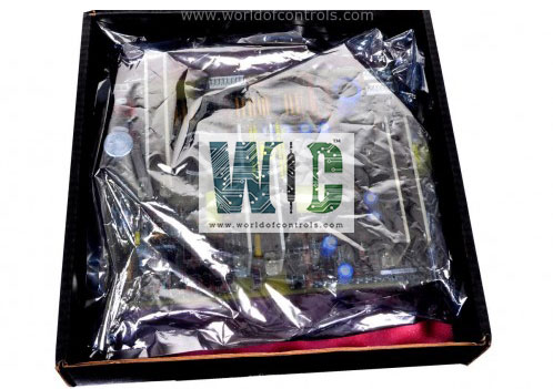
Part No.: IS200TREGH2BDD
Manufacturer: General Electric
Country of Manufacture: United States of America (USA)
Trip interlock isolation: Optical isolation to 1500 V on all inputs
Trip interlock filter: Hardware filter, 4 ms
Size: 17.8 cm wide x 33.02 cm, high
Technology: Surface-mount
Temperature rating: 30 to 60 oC
Product Type: Turbine Emergency Trip Board
Availability: In Stock
Series: Mark VI
Functional Description
IS200TREGH2BDD is a Turbine Emergency Trip Board developed by GE. It is a part of Mark VI control system. The Turbine Trip Regulator provides power to three emergency trip solenoids and is under the control of the I/O controller within the system. This configuration allows for seamless integration of emergency trip functionalities into the turbine control system.
Features
- Emergency Trip Solenoids: Designed to supply power to three emergency trip solenoids, ensuring their reliable operation during critical situations.
- Connection: Each of the three trip solenoids can be connected between the TREG and TRPG terminal boards, facilitating efficient power distribution and control.
- Power Supply: Responsible for providing the positive side of the DC power required for the operation of the solenoids, while TRPG handles the negative side, ensuring a balanced power distribution system.
- Control: The I/O controller takes charge of overseeing the emergency overspeed protection and emergency stop functions. Additionally, it manages the operation of the 12 relays integrated into the board.
- Relay Configuration: Among the 12 relays on the board, nine are grouped into three sets of three. These grouped relays are utilized to implement a voting mechanism for the inputs controlling the three trip solenoids, enhancing redundancy and reliability in critical operations.
Solenoid Trip Test
- Online Testing: The application software embedded within the controller facilitates the execution of solenoid trip tests. These tests can be initiated individually for each trip solenoid, providing a comprehensive assessment of their functionality.
- Manual Tripping: During online tests, solenoids can be manually tripped one at a time. This can be achieved either through the PTR (Primary Trip Relay) relays controlled by the controller or through the ETR (Emergency Trip Relay) relays managed by the protection module.
- Positive Indication: To confirm the successful tripping of each solenoid, a contact from each solenoid circuit is looped back as a contact input. This setup ensures that a
- positive indication is received once the solenoid has been effectively tripped.
Offline Overspeed Tests: In addition to online tests, the system provides primary and emergency offline overspeed tests. These tests are essential for validating the actual trips resulting from simulated overspeed conditions generated by the software.
Trip interlock system
- The trip interlock system comprises two primary components, H1 and H2, each serving distinct voltage requirements and operational parameters. H1 operates within a nominal voltage range of 125 V DC, with a floating capacity ranging from 100 V to 145 V DC. This component is crucial for facilitating interlock functionalities, ensuring safety mechanisms are engaged within the specified voltage parameters. For H1 in 125 V DC applications, circuits draw 2.5 mA, characterized by a resistance of 50 ohm, enabling reliable interlock operation.
- In contrast, H2 operates at a nominal voltage of 24 V DC, with a floating range spanning from 18.5 V to 32 V DC. Similar to H1, H2 plays a pivotal role in trip interlock systems, albeit for applications requiring lower voltage thresholds. The 24 V DC circuitry draws 2.5 mA, featuring a resistance of 10 ohm, ensuring consistent and efficient interlock functionality within the designated voltage range.
- These trip interlock specifications provide clear guidelines for voltage parameters and current draw limits, ensuring the reliable operation of safety mechanisms and interlock functionalities in critical systems and applications.
The WOC team is always available to help you with your Mark VI requirements. For more information, please contact WOC.
Frequently Asked Questions
What is IS200TREGH2BDD?
It is a Turbine Emergency Trip Board developed by GE under the Mark VI series.
How are trip solenoids tested in the system?
The application software within the controller initiates tests of the trip solenoids, facilitating a comprehensive evaluation of their functionality.
What testing capabilities are provided online?
Online tests enable individual trip solenoids to be manually tripped, one at a time. This can be achieved either through the PTR relays from the controller or via the ETR relays from the protection module.
How is the tripped status of solenoids confirmed?
To verify successful tripping, a contact from each solenoid circuit is wired back as a contact input, providing a positive indication that the solenoid has been tripped.
