SPECIFICATIONS
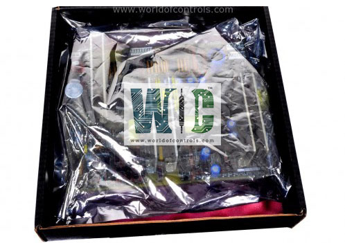
Part No.: IS200TREGH2BDB
Manufacturer: General Electric
Country of Manufacture: United States of America (USA)
Size: 17.8 cm wide x 33.02 cm, high
Trip interlock isolation Optical: isolation to 1500 V on all inputs
Trip interlock filter: Hardware filter, 4 ms
Product Type: Turbine Trip Terminal Board
Availability: In Stock
Series: Mark VIe
Functional Description
IS200TREGH2BDB is a turbine trip terminal board developed by GE. It is part of the Mark VIe series. The TREG serves as a crucial component within the turbine system, providing power to three emergency trip solenoids and functioning under the control of the I/O controller. The primary function of the TREG is to supply power to three emergency trip solenoids, vital for initiating emergency shutdowns in the turbine system. It operates under the complete control and management of the I/O controller, responding to commands and instructions from the controller.
Features
- Redundant TREG Applications: In redundant TREG setups, it is common to find a combination of one H3B and one H4B board used together. This configuration ensures redundancy and reliability in power supply and control mechanisms, maintaining system integrity even in the event of a failure in one component.
- Importance of the Correct Board Type for System Repairs: It is essential to ensure that system repairs involving board replacements are conducted with the correct board type. This maintenance practice is crucial to preserving the intended control power separation designed within these systems and ensuring their proper functioning.
- Control Mechanism through the PPRO Pack on SPRO: Control over the TREG is facilitated by the PPRO (Primary Protection) pack, which typically plugs into the D-type connectors on the SPRO (Secondary Protection) board. The PPRO pack interfaces with and controls the TREG through this connection.
- Cabling and Connection Setup: Cables featuring molded plugs serve as the connection interface between the TREG and the SPRO board. These cables enable communication and interaction between these components, ensuring proper functionality and control over the emergency trip solenoids.
- System Reliability and Redundancy: The use of redundant boards and the meticulous connection setup between components, such as the TREG, PPRO pack, and SPRO board, emphasizes the system's reliability, redundancy, and its ability to maintain critical safety measures within the turbine system.
Product Attributes
- Trip Solenoid Rating: The trip solenoids are rated at 24 V DC with an alternate 1 A draw. This indicates the voltage requirement and the maximum current draw during their operation.
- Trip Solenoid Circuits: The circuits for trip solenoids are rated for NEMA class E creepage and clearance standards, ensuring safe and reliable operation. They are designed to comply with specific safety requirements for insulation distances and clearance in electrical equipment. These circuits can safely clear a 15 A fuse even when all circuits are fully loaded, indicating robustness and safety in case of overcurrent scenarios.
- Solenoid Response Time: The solenoid L/R time constant is specified as 0.1 second. This parameter refers to the time constant calculated by the inductance (L) divided by the resistance (R) of the solenoid coil, determining the response time for the solenoid to activate or deactivate.
- Suppression Method: Metal Oxide Varistor (MOV) is employed across the solenoid for suppression purposes. MOVs are voltage-dependent resistors that provide protection against voltage spikes and surges, safeguarding the solenoids from transient electrical events.
- Relay Outputs: There are three economizer relay outputs available, each featuring a two-second delay before energization. These relays serve specific functions in the system and have a designated delay to control the timing of their activation.
- Driver to Breaker Relay (K25A on TTUR) and Servo Clamp Relay (TSVO): The driver sends signals to the breaker relay K25A on TTUR and the servo clamp relay on TSVO. These relays play critical roles in controlling and managing various safety or operational aspects within the turbine system.
- Solenoid Control Relay Contacts: Contacts within the solenoid control relays are rated to interrupt inductive solenoid loads at 125 V DC and 1 A. This specification ensures their capability to manage and control the solenoid loads within specified voltage and current limits. The permissible bus voltage for these contacts varies from 70 to 145 V DC, highlighting their tolerance range for varying bus voltages in the system.
The WOC team is always available to help you with your Mark VIe requirements. For more information, please contact WOC.
Frequently Asked Questions
What is IS200TREGH2BDB?
It is a Turbine Trip Terminal Board developed by GE under the Mark VIe series.
What components are connected to the first I/O terminal block?
The first I/O terminal block connects critical safety components, including three trip solenoids, economizing resistors, and the emergency stop mechanism.
How many trip interlocks can be connected, and where are they wired?
Up to seven trip interlocks can be wired to the second I/O terminal block, providing additional safety measures or control mechanisms within the system.
