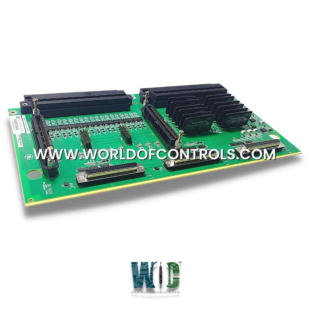
SPECIFICATIONS
Part No.: IS200TREAH1A
Manufacturer: General Electric
Country of Manufacture: United States of America (USA)
Temperature: -30 to +65oC
Technology: Surface mount
Product Type: turbine emergency trip terminal board
Availability: In Stock
Series: Mark VIe
Functional Description
IS200TREAH1A is a turbine emergency trip terminal board developed by GE. It is part of the Mark VIe series. The Aero derivative Turbine Emergency Trip terminal board combined with the WREA option card, works with turbine I/O packs as part of the Mark VIe system.
Features
- Customer Input Terminals: Available through two 24-point pluggable barrier terminal blocks or 48 pluggable Euro-style box terminals (H3A or S3A).
- Pulse Rate Devices: Six passive pulse rate devices (supporting up to three shafts with two sensors each) that sense a toothed wheel to measure turbine speed.
- Solid-State Output Contacts: Three TMR voted 24 V DC output contacts designed to trip the system.
- Voltage Detection Circuits: Four circuits for detecting voltages between 24-125 V DC, used for monitoring trip strings.
- Contact Inputs: Four 24 V DC contact inputs on WREAH1A or WREAS1A provide additional hardware or conditional trip inputs, with wetting power supplied via the JH1 connector on WREA.
- Speed Repeater Outputs: Each of the six-speed inputs has a corresponding repeater output that reproduces the speed pulse rate signals, transmitted through an RS-232 or RS-422 interface.
Installation
- Begin by carefully aligning the two connectors on the WREA with those on the terminal board. As you handle the WREA, note that the bottom of the board is identified by the row of configuration jumpers. This end should be positioned correctly to ensure proper connection. The connectors on both boards are keyed, meaning they are designed to only mate when properly aligned. This feature helps to prevent incorrect installation and ensures a secure connection.
- Once you have aligned the WREA with the terminal board, firmly press down on the four screw heads that surround the connector area. This step is crucial as it seats the connection securely, ensuring that the WREA is fully integrated with the board. Continue to press until the WREA is fully mounted, which is indicated when the board can no longer be pushed any farther into place.
- For installations involving H1 and S1 board variants, voltage detection circuits, trip contact inputs, and relay outputs should be connected to the I/O terminal blocks labeled TB1.
- Passive pulse rate pick-ups, which are responsible for measuring turbine speed, should be connected to terminal block TB2. Each terminal block (TB1 and TB2) is secured with two screws and is equipped with 24 terminals, capable of accepting wires up to 12 AWG. A shield termination strip, which is connected to the chassis ground, is positioned immediately to the left of each terminal block to provide proper grounding and reduce electrical noise.
- For H3 and S3 board variants, the wiring process is slightly different. Voltage detection circuits, trip contact inputs, and relay outputs should be connected to the I/O box terminals located at the top of the board. Passive pulse rate pick-ups should be connected to the lower terminals on the board. All terminals on these variants plug into a header on the board and can accept up to a single 12 AWG wire, ensuring a secure and reliable connection.
The WOC team is always available to help you with your Mark VIe requirements. For more information, please contact WOC.
Frequently Asked Questions
What is IS200TREAH1A?
It is a turbine emergency trip terminal board developed by GE under the Mark VIe series.
What should I do if I need to remove the board for servicing?
If you need to service the TRA fanning jumpers or any other components, you must first remove the option card. Follow the outlined procedure to carefully detach and later reattach the WREA to the board.
How do I properly align the option board with the terminal board?
Align the connectors on the option board with those, ensuring the bottom of the WREA board (where the configuration jumpers are located) is correctly positioned. The connectors are keyed and will only mate when properly aligned, preventing incorrect installation.
What indicates that the WREA is fully mounted to the board?
It is fully mounted when it cannot be pushed any farther. This ensures a secure connection. Press down firmly on the four screw heads surrounding the connector area to seat the connection properly.
