SPECIFICATIONS
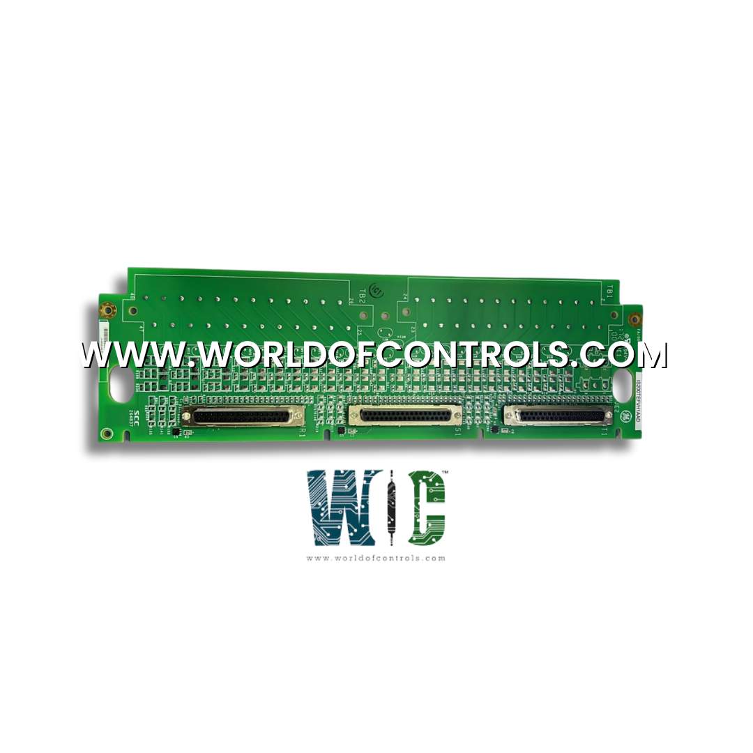
Part No.: IS200TEFVH1A
Manufacturer: General Electric
Product Type: Electric Fuel Valve Gateway
Size: 8.26 cm high x 4.19 cm wide x 12.1 cm deep
Technology: Surface mount
Temperature Operating: -30 to 65oC
Availability: In Stock
Country of Manufacture: United States (USA)
Series: Mark VIe
Functional Description
IS200TEFVH1A is an Electric Fuel Valve Gateway developed by GE. It is a part of Mark VIe control system. Electric Fuel Valve Gateway (PEFV) serves as an Ethernet gateway linking the Mark VIe I/O Ethernet network with an electric fuel valve interface module, known as the Digital Valve Positioner (DVP), manufactured by Woodward Controls. This module facilitates communication via the Ethernet Global Data (EGD) protocol.
Product Features
- The PEFV comprises a processor board standard for all Mark VIe I/O packs. It features two RJ45 Ethernet connectors- one connects to the I/O Ethernet network and the other directly links to the DVP. Additionally, a 3-pin connector is used to supply power to the pack.
- The dual RJ45 connectors are essential for the PEFV's operation. The first connector integrates the PEFV with the Mark VIe I/O Ethernet network, ensuring seamless communication within the control system. The second connector directly interfaces with the DVP, enabling precise control and monitoring of the electric fuel valve.
- PEFV is powered through a 3-pin connector, which provides the necessary electrical input for its operations. This configuration ensures the gateway can perform reliably, maintaining efficient communication and control within the Mark VIe framework.
Installation Procedure
- Mount the Board - Begin by securely mounting the board in its designated location, ensuring it is firmly in place to provide a stable base for subsequent installations.
- Plug in PEFVs for Triple Modular Redundancy (TMR) - Directly plug three PEFVs into the terminal board connectors. This setup provides triple modular redundancy, enhancing the system's reliability and fault tolerance.
- Mechanically Secure the Packs - Mechanically secure the packs using the threaded inserts located adjacent to the Ethernet ports. These inserts should connect to a mounting bracket specific to the terminal board type. Adjust the bracket to ensure that no right-angle force is applied to the DC-37 pin connector between the pack and the terminal board. This adjustment is only required once during the product's lifetime.
- Connect Ethernet Cables - Plug one Ethernet cable into the I/O Ethernet network and connect the other Ethernet cable to the corresponding network connector on the Woodward DVP. The pack will operate with connections made to either port. If the connections are modified, the pack must be rebooted. Standard practice is to connect ENET1 to the network associated with the I/O Ethernet network.
- Apply Power - Power is applied to the connector on the side of the pack. The PEFV has an inherent soft-start capability that controls current inrush upon power application.
- Configure the PEFV - Configure the PEFV as necessary according to the system requirements and operational parameters. Ensure all settings are correctly applied to achieve optimal performance.
Power Management
- Soft Start Mechanism: The power management system includes a soft start feature to control the current inrush during the initial application of power. This helps prevent sudden surges that could potentially damage components or cause system instability.
- Fast Current Limit Function: After power is applied, the circuit employs a fast current limit function. This mechanism quickly limits the current to prevent failures within the pack or terminal board from propagating back into the 28 V power system. By containing potential issues, it helps maintain overall system integrity and prevents widespread failures.
- Power Indicator (PWR): The I/O pack is equipped with a green PWR indicator light that signals the presence and proper functioning of the power supply. When the power is applied correctly and the system is operating as expected, this indicator will be illuminated. If the fast current limit function activates due to an issue, the PWR indicator will turn off. This serves as an alert to the user that there is a problem requiring attention. Once the issue is resolved, the indicator will light up again, signaling a return to normal operation
World of Controls has the most comprehensive collection of GE Mark VIe components. Please contact WOC as soon as possible if you require any extra information.
Frequently Asked Questions
What is IS200TEFVH1A?
It is an Electric Fuel Valve Gateway developed by GE
What do the two indicator LEDs on each serial channel represent?
Each serial channel has two indicator LEDs- the TX LED and the RX LED. The TX LED flashes when the PEFV transmits data from a port, while the RX LED flashes when the port is receiving data.
What does the green LED labeled PWR indicate?
The green LED labeled PWR indicates the presence of control power. When this LED is lit, it signifies that the PEFV is receiving power and is operational.
What are the critical faults that cause the red ATTN LED to be solid on?
Critical faults include detected hardware failures on the processor or acquisition boards or the absence of application code loaded onto the pack.
