SPECIFICATIONS
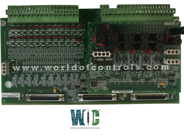
Part No.: IS200TDBTH6ABB
Manufacturer: General Electric
Country of Manufacture: United States of America (USA)
Size: 33.0 cm high x 17.8 cm wide
Technology: Surface mount
OperatingTemperature : -30 to 65 oC
Product Type: Input/Relay Output Terminal Board
Availability: In Stock
Series: Mark VIe
Functional Description
IS200TDBTH6ABB is a Input/Relay Output Terminal Board developed by GE. It is part of the Mark VIe series.The board serves as a Triple Modular Redundant (TMR) contact input/output terminal board that offers flexibility in mounting options-either DIN-rail or flat mounting. Its features and functionalities are tailored to cater to various voltage inputs and relay output requirements. Here's an expanded explanation:
Input and Output Capabilities
- The TDBT board accommodates 24 group isolated contact inputs that can receive nominal wetting voltages of 24, 48, or 125 volts direct current (V DC) from an external source.
- These inputs are designed to handle a variety of voltage ranges to suit different system configurations.
- The contact inputs are equipped with noise suppression mechanisms to safeguard against surges and high-frequency noise, ensuring the reliability and integrity of the input signals received by the board.
Relay Output Functionality
- The TDBT board features 12 form-C relay outputs, offering versatile control and switching capabilities. These relay outputs are capable of handling various tasks within the system, providing flexibility and functionality.
- It supports expansion through an option card, allowing for the augmentation of relay functions. This expandability feature enables customization and adaptation of the board to meet specific operational requirements.
Integration with Mark VIe Systems and PDIO I/O Pack
- In Mark VIe systems, the PDIO (Programmable Digital Input/Output) I/O pack interfaces and collaborates with the TDBT board. Three PDIO packs connect via D-type connectors and communicate with the system controllers through Ethernet connectivity.
- Specifically, the module provides three connection points for PDIO integration. In a setup involving dual controllers, PDIO connections are allocated as follows: connector JR1 to the R controller, JS1 to the S controller, and JT1 to both R and S controllers. For TMR controllers, a network connection is dedicated to each PDIO, individually linked to the respective controller.
Operational Considerations
- It's important to note that the TDBT board is not optimized to function correctly with a single PDIO I/O pack.
- Its design and functionality are oriented towards configurations involving multiple controllers, ensuring redundancy and robust operation within TMR systems.
Installation
- Mounting Options:
- The board, in conjunction with a plastic insulator, can be mounted onto a sheet metal carrier. This carrier can then be installed onto a DIN rail, providing a convenient and secure mounting option.
- Alternatively, the TDBT board and insulator assembly can be fixed onto a sheet metal assembly, which is then securely bolted inside a cabinet. This method provides an alternative mounting arrangement, suitable for specific cabinet configurations.
- Terminal Connections:
- The connections to the TDBT board are established through two sets of 48 terminal blocks.
- The upper set of terminals, labeled as TB1, is dedicated to connecting to the relay portion of the TDBT board. These connections enable interfacing with and controlling the relay functionalities offered by the board.
- The lower set of terminals, labeled as TB2, is intended for establishing connections to the contact input circuits of the TDBT board. These connections facilitate the input signals for the contact inputs, providing crucial information to the board.
- Wiring Details:
- Typically, 18 AWG wires are used for making the connections between the terminal blocks and the TDBT board. This gauge of wire is commonly suitable for handling the required current and ensuring proper connectivity.
- Screw Assignments and Shield Termination:
- The screw assignments for the two sets of terminals (TB1 and TB2) are identical to those found on the SRLY relay board and the STCI contact input terminal board. This standardization simplifies the installation process and ensures consistency across different board configurations.
- Shields, intended for grounding and noise suppression purposes, should be terminated on a separate bracket to maintain proper grounding and reduce the risk of electromagnetic interference.
The WOC team is always available to help you with your Mark VIe requirements. For more information, please contact WOC.
Frequently Asked Questions
What is IS200TDBTH6ABB?
It is an Input/Relay Output Terminal Board developed by GE under the Mark VIe series.
What is the threshold voltage for the contact inputs, and how is it determined?
The threshold voltage for contact inputs is set at 50 percent of the wetting voltage, serving as a reference point for signal detection within the specified voltage ranges.
Are there limitations on contact input currents for the board?
Yes, contact input currents are limited to 2.5 mA for the first 21 circuits and 10 mA for circuits 22 through 24, ensuring controlled current flow within specific circuit ranges.
How is the 24V DC supply on TDBTH2 regulated in terms of current limitations and safety measures?
The 24V DC supply is limited to 0.5A using resettable polymer positive temperature coefficient (PTC) fuses, providing safety and preventing overcurrent situations.
