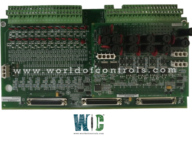
World Of Controls understands the criticality of your requirement and works towards reducing the lead time as much as possible.
IS200TDBTH4A - Contact Input/Relay Output Terminal Board is available in stock which ships the same day.
IS200TDBTH4A - Contact Input/Relay Output Terminal Board comes in UNUSED as well as REBUILT condition.
To avail our best deals for IS200TDBTH4A - Contact Input/Relay Output Terminal Board, contact us and we will get back to you within 24 hours.
SPECIFICATIONS:
Part No.: IS200TDBTH4A
Manufacturer: General Electric
Product Type: Contact Input/Relay Output Terminal Board
Series: Mark VIe
Number of Channels: 24
Wetting voltage: 24 V dc
Input current: Input current
Input filter Hardware filter: 4 ms
Description: I/O Terminal Board
Ac input frequency: 480 Hz maximum
Operating Temperature: -30 to 65°C
Contact material: Silver cad-oxide
Number of relay channels on one TDBT board: 12
Max load current: Max load current
Technology: Surface-mount
Max response time: 25 ms
AC voltage rejection: 12 V rms
Availability: In Stock
Size: 17.8 cm wide x 33.02 cm
Country of Manufacture: United States (USA)
Manual: GEH-6721D
FUNCTIONAL DESCRIPTION:
IS200TDBTH4A is a Contact Input/Relay Output Terminal Board manufactured and designed by General Electric and is part of the Mark VIe Series used in GE Distributed turbine control systems. The TDBT board is a TMR contact input/output terminal board designed for mounting on DIN rails or flat surfaces. It supports 24 group-isolated contact inputs, powered by an external source providing nominal wetting voltages of 24, 48, or 125 V DC. These inputs are equipped with noise suppression to guard against surges and high-frequency interference. The board features 12 form-C relay outputs and can accommodate an optional card to enhance relay functionality.
In Mark VIe systems, the TDBT works with the PDIO I/O pack, which connects via three D-type connectors and communicates with controllers through Ethernet. Three connection points are available for PDIO integration. In dual-controller setups, the PDIO connected to JR1 links to the R controller, JS1 to the S controller, and JT1 connects to both R and S controllers. For TMR controllers, each PDIO is networked to its corresponding controller. The TDBT is not intended for use with a single PDIO I/O pack, as it requires multiple connections for proper functionality.
INSTALLATION:
The TDBT board, along with a plastic insulator, can be mounted on a sheet metal carrier that attaches to a DIN rail. Alternatively, it can be installed on a sheet metal assembly designed for bolting inside a cabinet. Connections are made directly to two sets of 48-terminal blocks, typically using #18 AWG wiring. The upper terminal block, TB1, is designated for relay connections, while the lower terminal block, TB2, is used for contact input circuits. The screw assignments for these terminals are consistent with those on the SRLY relay board and the STCI contact input terminal board. Shielding should be grounded using a separate bracket.
OPERATION:
The contact input functionality and onboard signal conditioning of the TDBT board are equivalent to those of the STCI, configured for wetting voltages of 24, 48, and 125 V DC. The corresponding input wetting voltage ranges are 16–32 V DC, 32–64 V DC, and 100–145 V DC, with threshold voltages set at 50% of the wetting voltage. Detailed contact sensing circuit diagrams are included in the I/O pack documentation.
Input currents are limited by resistance to 2.5 mA for circuits 1–21 and 10 mA for circuits 22–24. The 24 V DC supply on the TDBTH2 is restricted to 0.5 A using resettable polymer PTC fuses. Filters positioned near the signal entry points mitigate high-frequency noise and surges. The discrete input voltage signals are processed by the I/O pack, which routes them through optical isolators for conversion to digital form before transmitting them to the controller.
WOC has the largest stock of Replacement Parts for GE Distributed turbine control systems. We can also repair your faulty boards and supply unused and rebuilt boards backed up with a warranty. Our team of experts is available round the clock to support your OEM needs. Our team of experts at WOC is happy to assist you with any of your automation requirements. For pricing and availability on parts and repairs, kindly contact our team by phone or email.
What is the primary function of the TDBT board?
The TDBT board serves as a TMR contact input/output terminal board, handling isolated contact inputs and form-C relay outputs for industrial control systems.
What types of voltages are supported for contact inputs?
The board supports nominal wetting voltages of 24 V DC, 48 V DC, and 125 V DC, with input voltage ranges of 16–32 V DC, 32–64 V DC, and 100–145 V DC, respectively.
How does the board process discrete input signals?
Discrete input signals are routed to the I/O processor, passed through optical isolators for digital conversion, and then sent to the system controller.