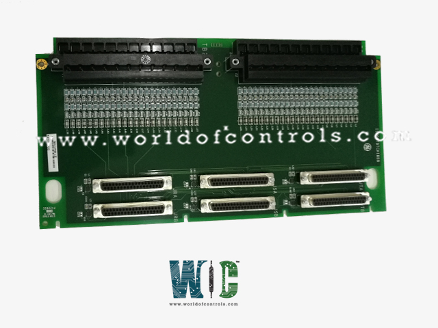
World Of Controls understands the criticality of your requirement and works towards reducing the lead time as much as possible.
IS200TBTCS1C - Thermocouple Input Terminal Board is available in stock which ships the same day.
IS200TBTCS1C - Thermocouple Input Terminal Board comes in UNUSED as well as REBUILT condition.
To avail our best deals for IS200TBTCS1C - Thermocouple Input Terminal Board, contact us and we will get back to you within 24 hours.
SPECIFICATIONS:
Part Number: IS200TBTCS1C
Manufacturer: General Electric
Series: Mark VIe
Product Type: Thermocouple Input Terminal Board
Number of Channels: 24
Span: -8 mV to +45 mV
Technology: Surface Mount
Common Mode Voltage Range: ±5 V
Dimensions: 11.00 x 9.00 x 3.00
Operating temperature: 0 to 60 °C
No.of Ribbon Cable Connectors: Two, 20-pin
No.of VMEbus Connectors Two, 96-pin
No.of Analog Voltage Inputs: 6
Repair: 3-7 Day
Availability: In Stock
Country of Origin: United States
Manual: GEH-6721D
FUNCTIONAL DESCRIPTION:
IS200TBTCS1C is a Thermocouple Input Terminal Board manufactured and designed by General Electric as part of the Mark VIe Series used in GE Distributed Turbine Control Systems. The Thermocouple Input (TBTC) terminal board accepts 24-type E, J, K, S, or T thermocouple inputs. It accepts additional B, N, and R types of thermocouple inputs only when used with PTCCH2 in Mark VIe. These inputs are wired to two barrier-type blocks on the terminal board. TBTC communicates with the I/O processor through DC-type connectors. In the Mark VIe system, the PTCC I/O pack works with the TBTC board. Simplex, dual, and TMR systems are supported. In simplex systems, two PTCC packs plug into the TBTCH1C for a total of 24 inputs. With the TBTCH1B one, two, or three PTCC packs plug-in supporting a variety of system configurations, only 12 inputs are available.
INSTALLATION:
Connect the thermocouple wires directly to the two I/O terminal blocks. These removable blocks are mounted on the terminal board and held down with two screws. Each block has 24 terminals accepting up to #12 AWG wires. A shield terminal strip attached to chassis ground is located on the left side of each terminal block. In Mark VI systems, cable the TBTC J-type connectors to the I/O processors in the VME rack. In Mark VIe systems, plug the I/O packs directly into the TBTC J-type connectors. The number of cables or I/O packs depends on the level of redundancy required.
OPERATION:
The 24 thermocouple inputs can be grounded or ungrounded. They can be located up to 300 m (984 ft) from the turbine control panel with a maximum two-way cable resistance of 450 Ω. TBTC features high-frequency noise suppression and two CJ reference devices, The I/O processor performs the analog-to-digital conversion and the linearization for individual thermocouple types. In Mark VI simplex systems using TBTCH1C, one VTCC is used. In Mark VIe simplex systems, two PTCC packs plug into TBTC, obtaining 24 thermocouple inputs. For TMR systems using TBTCH1B, the thermocouple signals fan out to three J- connectors. The Mark VI system accommodates 24 inputs and the Mark VIe system accommodates 12 inputs. The TBTC terminal board supports all thermocouple spans documented for the associated thermocouple I/O processor.
THERMOCOUPLE COLD JUNCTIONS:
The CJ signals go into signal space and are available for monitoring. Normally the average of the two is used. Acceptable limits are configured, and if a CJ goes outside the limit, a logic signal is set. A 1 °F error in the CJ compensation will cause a 1°F error in the thermocouple reading. Hard-coded limits are set at -40 to 85°C (-40 to +185 oF), and if a CJ goes outside these, it is regarded as faulted. Most CJ failures are open or short-circuit. If the CJ is declared fault, the backup value is used, which can be derived from CJ readings on other terminal boards, or can be the configured default value.
WOC has the largest stock of OEM Replacement Parts for the GE Distributed Turbine Control Systems. We can also repair your faulty boards and supply unused and rebuilt boards backed up with a warranty. Our team of experts is available round the clock to support your OEM needs. Our team of experts at WOC is happy to assist you with any of your automation requirements. For pricing and availability on parts and repairs, kindly contact our team by phone or email.
What is the Thermocouple Input Terminal Board?
The Thermocouple Input Terminal Board is designed for use in GE Distributed Turbine Control Systems. It facilitates temperature measurement by accepting multiple thermocouple inputs, ensuring precise temperature monitoring and control in power generation and industrial automation applications.
How many thermocouple inputs does this board support?
This board supports 24 thermocouple inputs, making it suitable for large-scale industrial applications. It is compatible with thermocouple types E, J, K, S, and T by default. Additionally, when used with the PTCCH2 module in the Mark VIe system, it also supports thermocouple types B, N, and R. These inputs are connected to the board using two barrier-type terminal blocks.
What is the input voltage range for the thermocouple signals?
The input voltage range for the thermocouple signals spans from -8 mV to +45 mV, ensuring compatibility with different thermocouple types and their respective signal outputs.