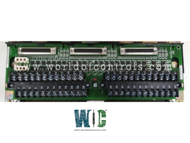
SPECIFICATIONS
Part No.: IS200TBCIH2CAA
Manufacturer: General Electric
Country of Manufacture: United States of America (USA)
Input filter: Hardware filter, 4 ms
Power consumption: 20.6 watts
Temperature rating: 0 to 60 oC
Size: 33.02 cm high x 10.16 cm wide
Temperature Operating: -30 to 65 o C
Product Type: contact input terminal board
Availability: In Stock
Series: Mark VI
Functional Description
IS200TBCIH2CAA is a contact input terminal board developed by GE. It is a part of Mark VI control system. The contact input terminal board accommodates 24 dry contact inputs, which are connected through two barrier-type terminal blocks. DC power is supplied to activate these contact inputs. Each input is equipped with noise suppression circuitry, designed to safeguard against surges and high-frequency noise. This feature ensures reliable operation by minimizing the risk of electrical interference, thereby enhancing the overall stability and performance of the system.
Wiring
- The wiring setup of the contact input terminal board (TBCI) involves connecting 24 dry contact inputs directly to two I/O terminal blocks mounted securely on the board. Each terminal block is held in place by two screws and can be easily unplugged when maintenance is required. These terminal blocks are specifically designed with 24 terminals each, capable of accepting wires as large as 12 AWG.
- Adjacent to each terminal block, positioned to the left, is a shield terminal strip. This strip is crucial as it connects directly to chassis ground, providing effective grounding and minimizing the risk of electrical interference. This grounding configuration helps maintain signal integrity and ensures the overall reliability of the terminal board assembly.
- Furthermore, each of the 24 contact inputs is equipped with noise suppression circuitry. This circuitry plays a vital role in protecting the inputs from potential damage caused by surges and high-frequency noise. By suppressing such electrical disturbances, the circuitry enhances the stability and performance of the entire system, making it suitable for environments where electrical noise is a concern.
Cabling Connections
- In the system configuration, cabling connections are tailored to the specific redundancy and system type requirements. For a simplex system, connector JR1 is utilized, providing a streamlined connection suitable for single-path operations. This configuration simplifies the cabling layout, optimizing installation and maintenance processes.
- In contrast, for a Triple Modular Redundant (TMR) system, all three connectors come into play. These connectors are strategically employed to ensure robust redundancy across the Mark VI or Mark VIe system architecture. Each connector plays a crucial role in maintaining continuous operation and fault tolerance, essential for critical applications where system reliability is paramount.
- Depending on the specific model of the Mark VI or Mark VIe system and the desired level of redundancy, cables or I/O packs are plugged into the appropriate connectors. This flexible approach accommodates varying operational needs, allowing for scalable configurations that align with application-specific requirements.
Operation
- In operation, the contact input terminal board employs filters to effectively mitigate high-frequency noise and suppress surges near the point of signal entry for each input. This ensures that the signals received are clean and reliable, enhancing the overall performance and stability of the system.
- The dry contact inputs on variant H1 of the TBCI are powered from a floating 125 V DC supply sourced from the turbine control system, operating within a range of 100 to 145 V DC. Prior to reaching each contact input, the 125 V DC bus is current-limited within the power distribution module. This precautionary measure helps regulate and protect against electrical overloads, ensuring the safe operation and longevity of the equipment. Versions H2 and H3 utilize lower voltage supplies as specified in the product's technical specifications, catering to different operational requirements and ensuring compatibility across various configurations.
- Upon receiving discrete input voltage signals, the TBCI's I/O processor transmits them through optical isolators. These isolators provide essential group isolation, safeguarding against electrical interference and ensuring signal integrity throughout transmission. The signals are then routed to the system controller, where they are processed and utilized to facilitate accurate control and monitoring functions.
The WOC team is always available to help you with your Mark VI requirements. For more information, please contact WOC.
Frequently Asked Questions
What is IS200TBCIH2CAA?
It is a contact input terminal board developed by GE under the Mark VI series.
How are the inputs connected to the terminal board in the contact input circuitry?
Each input in the contact input circuitry is connected to a pair of terminal points on the terminal board. One point (screw) serves as the positive DC source, while the second point provides the return path (input) to the board. This setup ensures clear and efficient electrical connections for each input.
What is the current loading capacity per terminal point in the contact input circuitry?
For the first 21 inputs on each terminal board, each terminal point can handle a current loading of 2.5 mA. The last three inputs on each board are designed to support higher loads, up to 10 mA per point, which facilitates interface compatibility with remote solid-state output electronics.
What standards does the contact input circuitry adhere to regarding safety and performance?
The contact input circuitry is designed to comply with NEMA Class G standards for creepage and clearance. This ensures sufficient spacing and insulation between electrical components, meeting safety requirements and minimizing the risk of electrical arcing or short circuits.
