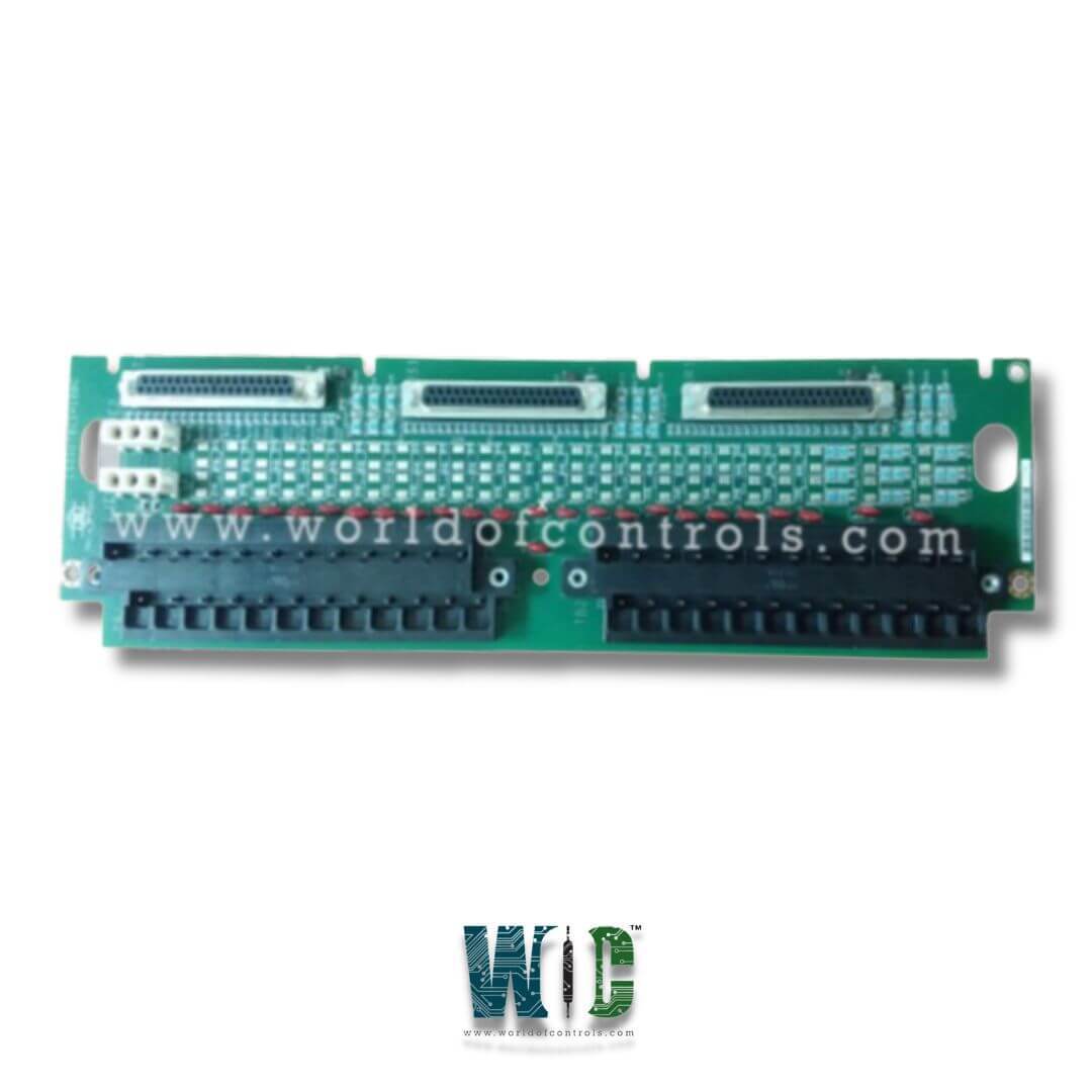
SPECIFICATIONS
Part No.: IS200TBCHIH2B
Manufacturer: General Electric
Country of Manufacture: United States of America (USA)
Voltage Rating: 24 V dc or 48 V dc.
Technology: Surface-mount
Product Type: Terminal Board
Availability: In Stock
Series: Mark VI
Functional Description
IS200TBCHIH2B is a Terminal Board developed by GE. It is part of Mark VI series. Mark VI integrates multiple functions, including control, monitoring, and protection, into a centralized system, enabling efficient operation and oversight of critical industrial processes.
System application software features
The application software operates sequentially and is visually represented in a dynamic state through a ladder diagram format, providing an intuitive interface for system control and monitoring. Maintenance personnel are empowered with various capabilities, enabling them to make alterations to the system:
- Modification Capabilities: Maintenance personnel possess the authority to add, delete, or modify analog loops, sequencing logic, tuning constants, and other essential parameters within the software framework. This flexibility allows for swift adaptations to accommodate evolving system requirements.
- User-Friendly Interface: The software interface facilitates ease of editing by enabling data points to be selected and seamlessly "dragged" across the screen from one functional block to another. This drag-and-drop functionality simplifies the editing process, enhancing efficiency in making changes or adjustments.
- Logic Forcing: Maintenance personnel can implement logic forcing, providing the ability to override system logic temporarily for diagnostic or testing purposes.
- Analog Forcing: Allows manual input of analog values, enabling simulation or testing of specific scenarios within the system.
Trending at Frame Rate: Real-time data visualization and analysis through trending features, enabling observation and analysis of system behavior at the frame rate level.
- Availability and Compatibility: The software maintenance tools, housed within the Control System Toolbox, are accessible via the Human-Machine Interface (HMI). Additionally, they are available as a standalone software package compatible with virtually any Windows 95 or NT based PC. This ensures accessibility and convenience for maintenance and troubleshooting tasks, even beyond the confines of the primary control system interface.
Terminal Block Features
- Terminal blocks play a crucial role in facilitating secure connections within the Mark VI system. Here are the key features of the 24-position pluggable barrier terminal block (179C9123BB) commonly used in Mark VI terminal boards:
- Material Composition: Constructed from a durable polyester resin material, providing excellent thermal resistance with a rating of 130°C (266 °F). This ensures reliability even in demanding operating conditions.
- Terminal Rating: Terminal block rated for 300 volts and 10 amperes, meeting UL Class C general industry standards. It offers a creepage of 0.375 inches (9.525 mm) and a strike of 0.250 inches (6.35 mm), ensuring safety and compatibility with various electrical components.
- Certification: UL and CSA code approved, complying with industry standards for safety and quality assurance. This certification underscores the terminal block's reliability and suitability for use in critical applications.
- Finishing: Screws finished in zinc clear chromate and contacts coated in tin, providing corrosion resistance and ensuring long-term performance and durability in diverse environmental conditions.
- Number Labeling: Each block screw is labeled with numbers 1 through 24 or 25 through 48 in white, facilitating easy identification and wiring of connections, streamlining installation and maintenance processes.
- Recommended Torque: The recommended screw tightening torque is 8 in lbs, ensuring optimal and secure connections without risk of over-tightening or damage to components.
Wiring and Circuit Checks
- Verification of Power Wiring: Verify that all incoming power wiring aligns precisely with the provided elementary drawings.
- Adherence to Approved Wiring Practices: Ensure that the incoming power wiring conforms strictly to approved wiring practices, as outlined earlier in this chapter.
- Inspection of Electrical Terminal Connections: Check that all electrical terminal connections are securely tightened to prevent any potential hazards.
- Detection of Wiring Damage: Inspect all wiring to ensure that none has been damaged or frayed during installation. If any damage is detected, promptly replace the affected wiring.
- Verification of Incoming Power: Confirm that the incoming power (125 V dc, 115 V ac, 230 V ac) matches the correct voltage and frequency specifications. Additionally, ensure that the power is clean and free of any noise interference.
- Adjustment of AC to DC Converters (if applicable): If AC to DC converters are utilized, verify that they are set to the correct voltage (115 V or 230 V ac) by selecting the appropriate jumper positions (JTX1 or JTX2) located on the front of the converter.
- Installation of BJS Jumper (if applicable): In installations comprising multiple PDMs interconnected within a 125 V dc system, ensure that the BJS jumper is installed in one and only one PDM. This arrangement is imperative to prevent impedance reduction to a level where the 125 V dc fails to meet the Not Hazardous Live requirement.
The WOC team is always available to help you with your Mark VI requirements. For more information, please contact WOC.
Frequently Asked Questions
What is IS200TBCHIH2B?
It is a Terminal Board developed by GE under the Mark VI series.
What are the available configurations for the Control Module in terms of slots?
The Control Module is available in either a 13-slot or 21-slot standard VME card rack.
How does the Control Module receive inputs?
Inputs are received by the Control Module through termination boards equipped with either barrier or box-type terminal blocks, facilitating passive signal conditioning.
What processing capabilities are included within each I/O card?
Each I/O card incorporates a TMS320C32 DSP (Digital Signal Processor) processor. This processor digitally filters the incoming data before converting it into a 32-bit IEEE-854 floating-point format.
