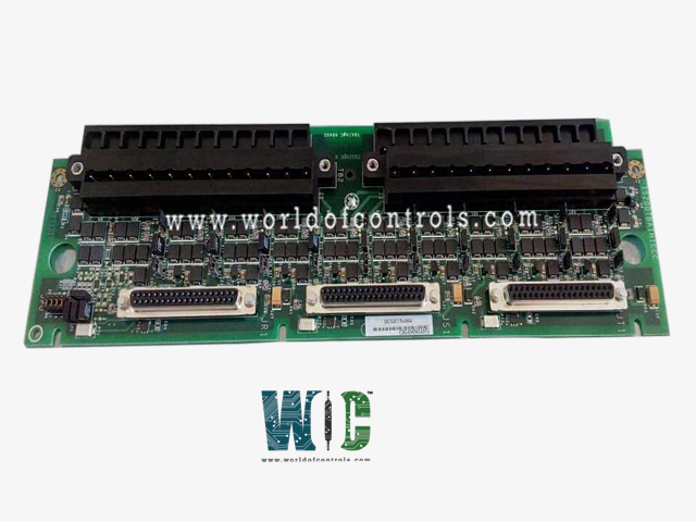
SPECIFICATIONS
Part No.: IS200TBAIH1CCC
Manufacturer: General Electric
Country of Manufacture: United States of America (USA)
Size: 10.16 cm wide x 33.02 cm high
Temperature rating: 30 to 65 oC
Product Type: analog input terminal board
Availability: In Stock
Series: Mark VIe
Functional Description
IS200TBAIH1CCC is an analog input terminal board developed by GE. It is a part of Mark VIe control system. The Analog Input Terminal Board is designed to support a total of 10 analog inputs and two outputs, offering a versatile interface for various types of transmitters. These inputs accommodate two-wire, three-wire, four-wire, or externally powered transmitters, ensuring flexibility and compatibility across different transmitter configurations. Moreover, the analog outputs can be configured for either 0-20 mA or 0-200 mA current output settings, providing adaptability to diverse operational requirements.
Features
- Noise Suppression and Protection:Inputs and outputs are fortified with specialized noise suppression circuitry, serving as a protective measure against surge and high-frequency noise. This integrated circuitry safeguards the integrity of the signals, ensuring accurate and reliable transmission of analog data without being affected by external interferences.
- Connectivity and Configuration Options: Equipped with three DC-37 pin connectors to facilitate connection to the I/O processors. Configuration options include either simplex connectivity via a single connector (JR1) or Triple Modular Redundant (TMR) setup, utilizing all three connectors. Connections can be established either through cables or directly to the electronics, offering flexible connectivity solutions tailored to specific system configurations and setups.
- TMR Functionality and Output Operation:In Triple Modular Redundant (TMR) applications, input signals are distributed or fanned out across the three connectors, designated for the R, S, and T controls. TMR outputs operate by aggregating the current from the three connected output drivers and determining the total current via a measuring shunt on the TBAI. Subsequently, presents this total current signal to the electronics for regulation, aligning it with the commanded setpoint for enhanced operational control and accuracy.
- Channel Configuration and Output Capabilities:Each terminal board boasts 12 channels, allocating 10 channels for Analog Input (AI) and reserving 2 channels for Analog Output (AO). The input span for transmitters ranges from 1-5 V DC derived from a 4-20 mA current input range. Furthermore, the outputs deliver 24 V each, providing a maximum output of 21 mA per connection, ensuring robust output capabilities for diverse operational demands.
Installation
The installation process for the Analog Input Terminal Board (TBAI) involves direct wiring of the 10 inputs and two outputs to two I/O terminal blocks mounted on the board. Each block is secured with two screws and features 24 terminals capable of accommodating wires up to #12 AWG. Adjacent to each terminal block, there's a designated shield terminal attachment point, crucial for proper shielding and minimizing interference during operation.- The TBAI is designed to support various types of analog inputs and outputs, providing compatibility with different transmitter configurations and voltage specifications. This includes support for two-wire, three-wire, four-wire, and externally powered transmitters, as well as voltage inputs spanning ±5 V or ±10 V DC. Additionally, the analog outputs can be configured for either 0-20 mA or 0-200 mA, ensuring adaptability across a wide range of industrial applications.
- The I/O terminal blocks, with their secure fastening and multiple terminals capable of handling sizable wires, facilitate stable and efficient connectivity for the inputs and outputs. The adjacent shield terminal attachment points add an extra layer of protection by enabling proper shielding against interference, ensuring reliable signal transmission and integrity within the system.
Configuration
The configuration process for the terminal board primarily relies on jumpers, offering a straightforward method to customize settings. Referring to the installation diagram provides the locations for these jumpers. The available jumper choices and their functions are detailed below:
- J1A through J8A Jumpers: These jumpers are responsible for selecting between current input or voltage input for the respective channels.
- J1B through J8B Jumpers: These jumpers determine whether the return is connected to the common or left open for each channel.
- J9A and J10A Jumpers: These jumpers facilitate the selection between 1 mA or 20 mA input current for specific channels.
- J9B and J10B Jumpers: These jumpers dictate whether the return is linked to the common or left open for the designated channels.
- Jumper J0: Jumper J0 sets the output for Output 1, allowing a choice between 20 mA or 200 mA configurations.
Additional Configuration Options
- Apart from the jumper-based configurations, further adjustments or settings for VAIC (Voltage Analog Input Configuration) or PAIC (Power Analog Input Configuration) can be performed using the toolbox. These configurations encompass a broader spectrum of adjustments and fine-tuning functionalities, enhancing the flexibility and customization potential of the terminal board beyond the basic jumper settings.
- The jumper-based configurations provide a convenient and accessible means to tailor specific input and output settings, while the toolbox enables more intricate adjustments, expanding the range of customization and optimization options available for the terminal board's functionalities.
The WOC team is always available to help you with your Mark VIe requirements. For more information, please contact WOC.
Frequently Asked Questions
What is IS200TBAIH1CCC?
It is an analog input terminal board developed by GE under the Mark VIe series.
Is there a power source available for transducers on the terminal board?
Yes, a 24 V DC power source is conveniently provided on the terminal board, ensuring consistent power availability for all connected transducers.
How are the input options configured on the terminal board?
The terminal board offers flexibility in input configurations using jumpers, allowing users to choose between current or voltage inputs. This adaptability caters to diverse transducer requirements.
Can the terminal board be used for Triple Modular Redundant (TMR) applications?
Yes, the terminal board is TMR-compatible, enabling its use in applications requiring redundancy. This feature ensures enhanced system reliability and redundancy when deployed in critical operational setups.
