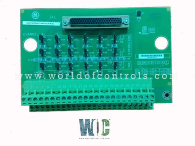
World Of Controls understands the criticality of your requirement and works towards reducing the lead time as much as possible.
IS200SSVPH2A - Servo Input/Output Terminal Board is available in stock which ships the same day.
IS200SSVPH2A - Servo Input/Output Terminal Board comes in UNUSED as well as REBUILT condition.
To avail our best deals for IS200SSVPH2A - Servo Input/Output Terminal Board, contact us and we will get back to you within 24 hours.
SPECIFICATIONS:
Part Number: IS200SSVPH2A
Manufacturer: General Electric
Series: Mark VIe
Product Type: Servo Input/Output Terminal Board
Number of Input channels: 6
Board Rating: 125 V dc
Number of outputs: 2
Power supply voltage: 28 V dc
Power supply current: 1.5 A dc
LVDT excitation output: 3.2 ±0.2 kHz
Generator current inputs: 0 to 5 A
Analog inputs Current inputs: 4-20 mA
Analog output current: 0-20 mA
Size: 15.875 cm high x 20.32 cm
Operating Temperature: -30 to +65°C
Technology: Surface Mount
Repair: 3-7 Day
Availability: In Stock
Weight: 2 lbs
Country of Origin: United States
Manual: GEH-6721_Vol_II V
FUNCTIONAL DESCRIPTION:
IS200SSVPH2A is a Servo Input/Output Terminal Board Manufactured and designed by General Electric as part of the Mark VIe Series used in GE Distributed Turbine Control Systems. It is used to connect two electro-hydraulic servo valves that control the steam valves. Valve positions are tracked using linear variable differential transformers (LVDT) or linear variable differential reluctance transformers (LVDR). The SSVP is specifically designed to work with the PSVP I/O pack and the WSVO servo driver but is not compatible with the VSVO board or the PSVO pack. It is a simple terminal board, but dual redundancy can be achieved by using two SSVPs with external input fanning. For TMR redundancy, three SSVPs are used, with the LVDT inputs being fanned externally by jumpers that share the signal between the SSVPs. A single 28 V DC supply connects via plug P28IN, and external trips from the protection module can be connected through plugs JD1 or JD2.
INSTALLATION:
Sensors and servo valves are connected directly to the TB1 I/O terminal block, which is secured by two screws and has 24 terminals that can accommodate wiring up to #12 AWG. A shield terminal strip, grounded to the chassis, is located to the left of the terminal block. External trip wiring connects via plugs JD1 or JD2.
Each SSVP servo output can power either a single coil in a three-coil electro-hydraulic servo-actuator or paralleled coils in a two-coil servo. To prevent thermal stress on the current driver in case of a short output, the user selects the appropriate current limiting resistor based on the coil's rated current. Jumpers JP1 and JP2 are used to select the resistor values for Servo 1 and Servo 2, respectively.
The P28 power input for the PSVP and WSVO comes through the P28IN connector on the SSVP. Switch SW1 enables the P28 bus, which powers the PSVP pack and the WSVO servo driver. The P28IN LED illuminates when 28 V DC is applied to the SSVP, but the P28ON LED will remain off until SW1 is switched to the P28ON position. A red PSVP_ONLY LED will light if a PSVO pack is mistakenly connected to the JA1 connector instead of a PSVP pack.
OPERATION:
The SSVP servo terminal board offers two channels with bi-directional servo current outputs, six channels for LVDT/R position feedback, two channels for LVDT/R excitation, and a single pulse rate input. For each servo control loop, users can choose to use one, two, or three LVDT/Rs. The pulse rate input is designed specifically for measuring the primary speed of a steam turbine and is not suitable for flow-type pulse-rate inputs.
Each servo output features a dedicated suicide relay controlled by firmware. When de-energized, this relay shorts the current output to common, and it can be reset to normal conditions via a manual reset command. Additionally, each servo output has an isolation relay to protect other connected servos from a short circuit caused by the failed servo. Diagnostic functions track the status of each servo’s voltage, current, and suicide relay.
Each of the servo output channels is designed to drive a single coil or parallel coils. The servo outputs are also designed to be paralleled as shown in the PSVP configuration section. Servo cable lengths up to 300 m (984 ft) are supported with a maximum two-way cable resistance of 15 Ω. Since there are many types of servo coils, a variety of bi-directional current sources are jumper-selectable.
WOC has the largest stock of OEM replacement parts for GE Distributed Turbine Control Systems. We can also repair your faulty boards and supply unused and rebuilt boards backed up with a warranty. Our team of experts is available round the clock to support your OEM needs. Our team of experts at WOC is happy to assist you with any of your automation requirements. For pricing and availability on parts and repairs, kindly contact our team by phone or email.
What does the SSVP servo terminal board do?
The SSVP servo terminal board connects to electro-hydraulic servo valves and manages the control and feedback systems required for precise steam valve actuation. It provides servo current outputs, LVDT/R position feedback, LVDT/R excitation, and a pulse rate input for steam turbine speed measurement.
How many LVDT/Rs can be connected to the SSVP board?
Each servo control loop can support one, two, or three LVDT/Rs, offering flexible configuration options depending on system requirements.
What power supply does the SSVP board use?
The SSVP requires a 28 V DC power input, supplied through the P28IN connector. An LED indicator shows if the 28 V DC has been applied, and another LED signals when the power is switched on.