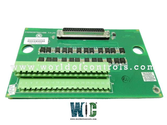
IS200SRTDH1ABB - Simplex RTD Board

IS200SRTDH1ABB - Simplex RTD Board IS200SRTDH1ABB - Simplex RTD Board

World Of Controls understands the criticality of your requirement and works towards reducing the lead time as much as possible.

IS200SRTDH1ABB - Simplex RTD Board is available in stock which ships the same day.

IS200SRTDH1ABB - Simplex RTD Board comes in UNUSED as well as REBUILT condition.

To avail our best deals for IS200SRTDH1ABB - Simplex RTD Board, contact us and we will get back to you within 24 hours.

SPECIFICATIONS

Part No.: IS200SRTDH1ABB
Manufacturer: General Electric
Country of Manufacture: United States of America (USA)
Temperature Operating: -30 to 65 o C
Number of channels: 8
Span: 0.3532 to 4.054 V
Product Type: Simplex RTD Board
Availability: In Stock
Series: Mark VIe

Functional Description

IS200SRTDH1ABB is an Simplex RTD Board developed by GE. It is a part of Mark VIe excitation system. The board represents a compact and efficient solution for integrating Resistance Temperature Detector (RTD) inputs within a control system setup. The board is designed to be compact, facilitating easy integration into control system setups. It is versatile, allowing for mounting on either a DIN-rail or a flat surface, providing flexibility to suit different installation requirements and environments.

Features

  • RTD Inputs: With eight RTD inputs, the board offers ample capacity to accommodate multiple temperature sensing points within the system. These inputs enable precise monitoring of temperature levels at various critical points, contributing to enhanced system performance and safety.
  • Connection to PRTD or VRTD I/O Processor: connects seamlessly to either a Programmable RTD (PRTD) or Voltage RTD (VRTD) Input/Output processor, serving as an interface between the RTD inputs and the processing unit. This connection facilitates efficient data transmission and processing, enabling real-time monitoring and control of temperature parameters.
  • High-Density Euro-Block Terminal Blocks: Mounted on the board are high-density Euro-block type terminal blocks, providing a reliable and secure connection interface for wiring RTD sensors. These terminal blocks offer robust connectivity, ensuring stable and consistent signal transmission between the RTD sensors and the processing unit.
  • On-Board ID Chip: An on-board ID chip is integrated into the board, serving to identify the board to the I/O processor for system diagnostic purposes. This identification capability enhances system troubleshooting and maintenance efforts by providing valuable information about the status and configuration of the board.

Operation

  • Excitation Current Supply: The board provides a 10 mA dc multiplexed excitation current to each sensor. This excitation current, though not continuous, ensures reliable and consistent operation of the RTD sensors. Each RTD sensor can be either grounded or ungrounded, providing flexibility in sensor configuration to suit different application requirements.
  • Signal Transmission Distance and Cable Resistance: The SRTD board allows for RTD sensors to be located up to 300 meters (984 feet) away from the turbine control cabinet. It supports a maximum two-way cable resistance of 15 Ω, ensuring signal integrity over long transmission distances. This capability enables the installation of RTD sensors in various locations within the system without compromising accuracy.
  • Noise Suppression and Signal Processing: Similar to the TRTD board, the SRTD board incorporates on-board noise suppression mechanisms to mitigate interference and ensure clean signal transmission. This feature helps maintain signal integrity and accuracy, even in electrically noisy environments.
  • Signal Sampling and Processing: The PRTD pack's A/D converter samples each RTD signal and the excitation current four times per second in normal mode scanning and 25 times per second in fast mode scanning. The sampling frequency is synchronized with the power system frequency, ensuring precise and synchronized data acquisition. Linearization for 15 different RTD types is performed by the processor, allowing for accurate temperature measurement across a wide range of operating conditions and sensor types.
  • Temperature Measurement and Linearization: The processor within the PRTD pack performs linearization of the signals to compensate for non-linearities inherent in sensors. This ensures accurate temperature measurement across the entire operating range. The selection of 15 RTD types allows for compatibility with various sensor configurations and temperature ranges.

The WOC team is always available to help you with your Mark VIe requirements. For more information, please contact WOC.

Frequently Asked Questions

What is IS200SRTDH1ABB?
It is an Simplex RTD Board developed by GE under the Mark VIe series.

What happens if hardware limits for an RTD input are exceeded?
If hardware limits are exceeded for an input, a logic signal is triggered, and the input is no longer scanned. Additionally, if any of the inputs exceed their hardware limits, it generates a composite diagnostic alarm (L3DIAG PRTD), referring to the entire board.

How are system limit checks configured for RTD inputs?
System limit checks for inputs are based on configurable high and low levels. These limits can be adjusted to generate alarms and configured for enable/disable, as well as latching/non-latching. The RESET SYS signal resets out-of-limit signals.

How is the resistance of each RTD checked?
The resistance of each RTD is continuously monitored and compared with the correct value. If the resistance is too high or too low, a fault is generated, indicating a potential issue with the RTD sensor.

What information is stored in the ID device for each connector?
Each connector on the board has its own ID device containing essential information such as the terminal board serial number, board type, revision number, and the connector's location. This information is coded into a read-only chip and is interrogated by the I/O processor board. Any mismatch encountered during interrogation results in a hardware incompatibility fault.

How are diagnostic signals managed and reset?
Diagnostic signals can be individually latched and then reset using the RESET DIA signal. This allows for efficient management and troubleshooting of diagnostic alarms, ensuring system integrity and reliability.