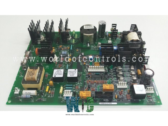
World Of Controls understands the criticality of your requirement and works towards reducing the lead time as much as possible.
IS200PSCAH1A - Serial Communication Input/Output Module is available in stock which ships the same day.
IS200PSCAH1A - Serial Communication Input/Output Module comes in UNUSED as well as REBUILT condition.
To avail our best deals for IS200PSCAH1A - Serial Communication Input/Output Module, contact us and we will get back to you within 24 hours.
SPECIFICATIONS:
Part Number: IS200PSCAH1A
Manufacturer: General Electric
Series: Mark VIe
Product Type: Serial Communication Input/Output Module
Number of channels: 6
Input Span: 1-5 V dc
Outputs: 24 V outputs
Technology: Surface Mount
Maximum Lead Resistance: 15Ω
Output load: 500 Ω
Analog output current: 0-20 mA
Operating temperature: -30 to 65 °C
Size: 8.26 cm high x 4.19 cm
Repair: 3-7 Day
Availability: In Stock
Country of Origin: United States
Manual: GEH-6721L
FUNCTIONAL DESCRIPTION:
IS200PSCAH1A is a Serial Communication Input/Output Module manufactured and designed by General Electric as part of the Mark VIe Series used in GE Distributed Control Systems. The Serial Communication Input/Output (PSCA) pack provides the electrical interface between one or two I/O Ethernet networks and a serial communications terminal board. The pack contains a processor board common to all Mark* VIe distributed I/O packs and a serial communications board. The communications board contains six serial transceiver channels, each of which can be individually configured to comply with RS-232, RS-422, or RS-485 half-duplex standards. Input to the pack is through dual RJ45 Ethernet connectors and a three-pin power input. Output is through a DC-62 pin connector that connects directly with the associated terminal board connector. One of the Ethernet ports can be used to support Ethernet Modbus communication on Simplex Networks. Visual diagnostics are provided through indicator LEDs.
INSTALLATION:
OPERATION:
The processor board is common to all Mark VIe Ethernet I/O packs or modules. It contains the following:
The processor board connects to an acquisition board specific to the I/O pack or module function. Upon application of input power, the soft-start circuit ramps up the voltage available on the processor board. The local power supplies are sequenced, and the processor reset is removed. The processor completes self-test routines and then loads application code specific to the I/O pack or module type from flash memory. The application code reads board ID information to ensure the correct matching of the application code, acquisition board, and terminal board. With a good match, the processor attempts to establish Ethernet communications, starting with a request of a network address. The address request uses the industry standard dynamic host configuration protocol (DHCP) and the unique identification read from the terminal board. After Ethernet initialization, the processor programs the on-board logic, runs the application, and enables the acquisition board to begin operation.
WOC has the largest stock of GE Distributed Control System Replacement Parts. We can also repair your faulty boards. WORLD OF CONTROLS can also supply unused and rebuilt backed up with a warranty. Our team of experts is available round the clock to support your OEM needs. Our team of experts at WOC is happy to assist you with any of your automation requirements. For pricing and availability on any parts and repairs, kindly get in touch with our team by phone or email.
What is a Serial Communication Input/Output Module?
A Serial Communication Input/Output Module is a hardware device that facilitates communication between a computer or microcontroller and external devices using serial communication protocols such as RS-232, RS-485, UART, or SPI. It typically provides both input and output capabilities, allowing the exchange of data between the connected devices.
What are the common applications of Serial Communication Input/Output Modules?
These modules are widely used in various industries and applications including industrial automation, embedded systems, robotics, telecommunications, data acquisition, and control systems. They enable seamless communication between different devices, sensors, actuators, and controllers.
How do Serial Communication Input/Output Modules interface with computers or microcontrollers?
These modules typically connect to computers or microcontrollers via standard serial communication interfaces such as USB (Universal Serial Bus), UART, or SPI. They may require appropriate drivers or software libraries to facilitate communication with the host system.