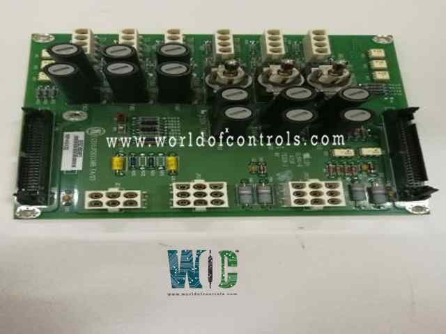
World Of Controls understands the criticality of your requirement and works towards reducing the lead time as much as possible.
IS200JPDEG1AAA - DC Battery Power Distribution Board is available in stock which ships the same day.
IS200JPDEG1AAA - DC Battery Power Distribution Board comes in UNUSED as well as REBUILT condition.
To avail our best deals for IS200JPDEG1AAA - DC Battery Power Distribution Board, contact us and we will get back to you within 24 hours.
SPECIFICATIONS:
Part Number: IS200JPDEG1AAA
Manufacturer: General Electric
Series: Mark VIe
Product Type: DC Battery Power Distribution Board
Number of Channels: 24
Input Isolation: 1500 V
AC Voltage Rejection: 60 V RMS
Voltage Range: 18 - 32 VDC
Mounting: DIN-rail mounting
Technology: Surface mount
Operating temperature: 0 to 60°C
Size: 16.51 cm high x 17.08 cm wide
Availability: In Stock
Country of Origin/Manufacturer: United States
Manual: GEH-6421H
FUNCTIONAL DESCRIPTION:
IS200JPDEG1AAA is a DC Battery Power Distribution Board manufactured and designed by General Electric as part of the Mark VIe Series used in GE Speedtronic Turbine Control Systems. The DC battery Power Distribution (JPDE) board receives dc power from a battery or power supply and distributes it to terminal boards and other system loads. JPDE supports a floating dc bus that is centered on earth using resistors and provides voltage feedback through PPDA to detect system ground faults. It provides inputs for two power supplies. JPDE can operate at either 24 V dc or 48 V dc. JPDE integrates into the PDM system feedback offered through the PPDA I/O pack. This board is limited by the current that can be passed through it using conventional board construction. JPDE does not supply power to bulk 500W - 24 V input/28V output power supplies providing I/O pack control power.
COMPATIBILITY:
The IS200JPDE board is compatible with the feedback signal P1/P2 connectors on JPDB, JPDF, JPDS, and JPDM leading to a PPDA I/O pack. These connectors receive critical feedback signals from multiple sources within the control system, providing essential data about operational parameters that allow for real-time adjustments. The board is compatible with connectors such as JPDB, JPDF, JPDS, and JPDM, each serving specific functions in connecting to different components of the system, including sensors and power supply elements.
INSTALLATION:
JPDE is base-mounted vertically on a metal bracket in a cabinet used by the PDM. There is a 50-pin diagnostic connector mounted on the top and bottom of the board. The IS200JPDE board is ground through the sheet metal bracket to the underlying back base. In most cases, this is the system FE. This dual connector setup simplifies monitoring and diagnosis without the need to remove the board from its mounted position. Overall, the configuration of the IS200JPDE board—its vertical mounting, dual diagnostic connectors, and effective grounding—contributes significantly to its functionality and reliability, ensuring efficient processing of feedback signals and robust communication with other components in the PDM and the turbine control system.
WOC has the largest stock of OEM Replacement Parts for GE Distributed Control Systems. We can also repair your faulty boards and supply unused and rebuilt boards backed up with a warranty. Our team of experts is available round the clock to support your OEM needs. Our team of experts at WOC is happy to assist you with any of your automation requirements. For pricing and availability on parts and repairs, kindly contact our team by phone or email.
What is a DC Battery Power Distribution Board?
A DC Battery Power Distribution Board is a system component that distributes direct current (DC) power from batteries to various devices and circuits within an electrical system, ensuring safe and efficient power management.
How does the distribution board ensure electrical safety?
The board incorporates protective devices such as fuses and circuit breakers to prevent overloads and short circuits. Additionally, proper grounding practices minimize electrical hazards and reduce the risk of equipment damage.
Can the distribution board handle different voltage levels?
Most DC Battery Power Distribution Boards are designed for specific voltage levels (e.g., 12V, 24V, 48V). Ensure you select a board that matches your system’s voltage requirements to avoid damage or malfunction.