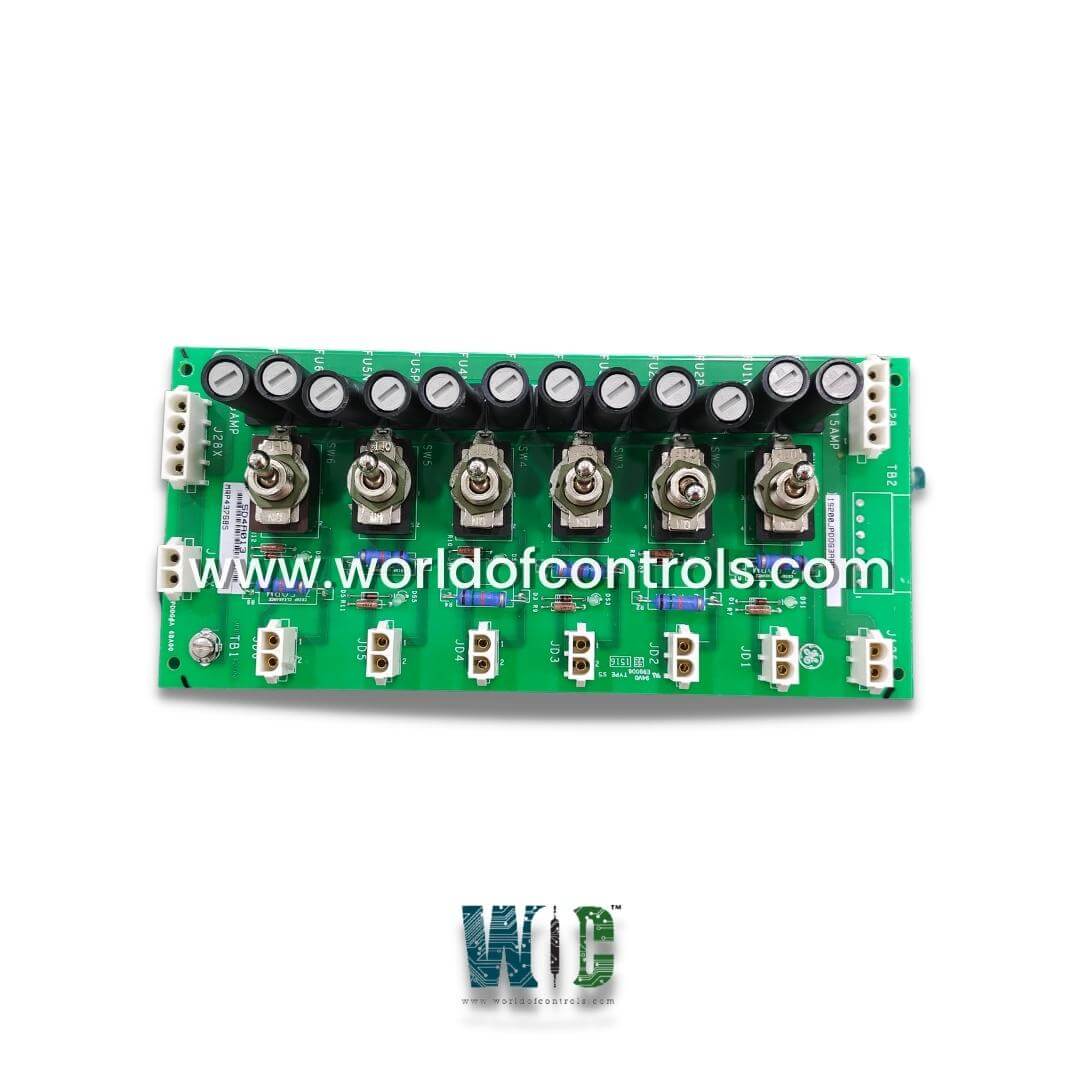
World Of Controls understands the criticality of your requirement and works towards reducing the lead time as much as possible.
IS200JPDDG3AAA - Power Distribution Module is available in stock which ships the same day.
IS200JPDDG3AAA - Power Distribution Module comes in UNUSED as well as REBUILT condition.
To avail our best deals for IS200JPDDG3AAA - Power Distribution Module, contact us and we will get back to you within 24 hours.
SPECIFICATIONS:
Part No: IS200JPDDG3AAA
Manufacturer: General Electric
Product Type: Power Distribution Module
Series: Mark VIe
Number of Channels: 12
Power to Contacts: 125 V dc
Inputs: 125 V dc, 15A
Output Voltage: 5V to 24V DC
Input span, transmitters: 1 - 5 V dc
Operating Voltage Range: 90V to 265V AC
Maximum lead resistance: 15 Ohm
Communication Protocols: Modbus
Technology: Surface Mount
Operating Temperature: -30°C to 65°C
Weight: 2.00 lbs
Mounting: DIN-rail mount
Size: 23.495 cm high x 10.795 cm
Country of Origin: USA
Availability: In stock
Manual: GEH-6721D
FUNCTIONAL DESCRIPTION:
IS200JPDDG3AAA is a Power Distribution Module manufactured and designed by General Electric and is part of the Mark VIe Series used in GE Distributed Turbine Control Systems. The JPDD board provides dc power distribution, power isolation, and branch circuit protection for control or I/O functions requiring 125 V dc or 24 V dc power. Typical applications include dc relay solenoid control power and contact wetting. Each output includes a fuse, a switch, and a lamp to indicate the presence of output voltage. JPDD is not intended for power distribution to the I/O packs. JPDAG1 provides fuses that are coordinated with the rating of the system wiring and connectors. JPDAG2 and G3 are used when fuse ratings coordinated with a specific application are required. Two different fuse sizes are provided to accommodate local fuse preferences.
INSTALLATION:
JPDD is held in a plastic holder, which mounts on a vertical DIN rail. When installing the JPDD, it is important to provide a ground lead from TB1 to the system ground. This creates a ground path for the metal switch bodies. Power input can be either 24 V dc or 125 V dc, but not both together. For cable destinations, refer to the circuit diagram. TB1 should be connected to the system ground.
OPERATION:
Multiple JPDD boards can receive power from a single Main Power Distribution Module branch circuit. Power input can be either 125 V dc or 24 V dc nominal. Two 2-Pin Mate-N-Lok connectors are provided for 125 V dc power. One connector receives input power and the other can be used to distribute 125 V dc power to another JPDD board in a daisy chain fashion. Two 4-pin Mate-N-Lok connectors are provided for 24 V dc power. These perform functions similar to those of the 2-pin connectors above. The 4-pin connector permits parallel connection of two pin-pairs for increased current capacity. It is expected that neither side of the dc power input is grounded.
Six identical output circuits are provided. Each output circuit includes two fuses, a switch with a pair of isolation contacts on each side of the output, and a green lamp to indicate the presence of voltage across the output terminals. The provision of a fuse and switch contact on each side of the DC path allows the use of this board with floating power sources.
WOC has the largest stock of OEM Replacement Parts for GE Distributed Control Systems. We can also repair your faulty boards and supply unused and rebuilt boards backed up with a warranty. Our team of experts is available round the clock to support your OEM needs. Our team of experts at WOC is happy to assist you with any of your automation requirements. For pricing and availability on parts and repairs, kindly contact our team by phone or email.
What are the main functions of a Power Distribution Module?
The primary function of a Power Distribution Module is to distribute electrical power efficiently while ensuring system safety and reliability. It protects circuits by integrating fuses or circuit breakers, preventing overload and short circuits.
What is the operating voltage range of a Power Distribution Module (PDM)?
The operating voltage range of a Power Distribution Module depends on the specific application and design. Common PDMs are designed for 12V, 24V, or 48V DC systems, typically found in automotive, marine, and industrial environments.
What is the current handling capacity of a PDM?
The current handling capacity of a PDM varies based on its design and intended use. Standard automotive PDMs typically support total system currents ranging from 30A to over 300A, while industrial-grade modules may handle even higher loads.