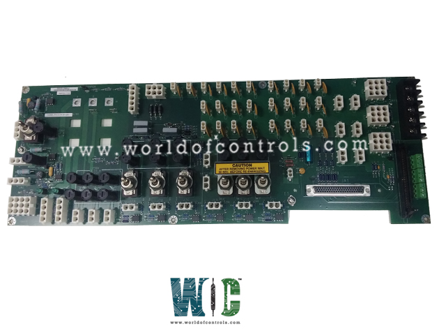
SPECIFICATIONS
Part No.: IS200JPDCG1ABA
Manufacturer: General Electric
Country of Manufacture: United States of America (USA)
Temperature Range:-30oC to 65oC
Board Size: 17.2 cm Wide x 48.26 cm High
Module Size: 17.78 cm Wide x 51.81 cm High x 7.62 cm Deep
Mounting: Back-panel mounting
Product Type: Power Distribution Module
Availability: In Stock
Series: Mark VIe
Functional Description
IS200JPDCG1ABA is a Power Distribution Module developed by GE. It is a part of Mark VIe control system. The module consolidates input and output functions from various previous designs, offering comprehensive distribution of power within the turbine control system. It facilitates distribution of 125 V dc, 115/230 V ac, and 28 V dc to other boards within the system, ensuring efficient power supply to all components.
Features
- Compatibility: The module is compatible with the Mark VIe Power Distribution System, offering seamless integration with existing system components. It can host a Power Distribution System Feedback (PPDA) pack, allowing for enhanced monitoring and control capabilities within the power distribution system.
- Diagnostic Feedback Handling: The module can receive diagnostic feedback signals from other distribution boards, consolidating these signals for further processing. These diagnostic signals can be routed to the PPDA I/O pack, providing comprehensive diagnostic capabilities for system maintenance and troubleshooting.
- Mounting Configuration: The I/O pack is intended to be mounted on the JPDC module, streamlining the integration process and optimizing space utilization within the control system. As such, no provision is made within the JPDC module to transmit diagnostic signals to another distribution board, as the focus is on consolidating diagnostic feedback within the PPDA I/O pack.
- Enhanced Efficiency and Reliability: By centralizing power distribution functions and diagnostic feedback handling, the module enhances the overall efficiency and reliability of the turbine control system. It minimizes the complexity of wiring and configuration, simplifying maintenance tasks and reducing downtime.
- Seamless Integration: Designed for seamless integration with the Mark VIe control system, the module offers plug-and-play compatibility, ensuring quick and hassle-free installation. Its compatibility with the PPDA further enhances system functionality, providing a comprehensive solution for power distribution and monitoring.
Input Power COnnections
- 125 V dc Battery Input Connections: One or two 125 V dc battery input connections, providing a reliable power source for the system. These connections are made through connectors JD1 and JD2, offering flexibility in the number of battery inputs based on system requirements.
- 125 V dc DACA Module Connection: In addition to battery inputs, the module can also receive power from a 125 V dc DACA module. This connection is established using connector JZ2, enabling seamless integration with the DACA module for enhanced functionality and control.
- 115 or 230 V ac Input: The module is capable of accepting input from both 115 V and 230 V ac power sources. This input is applied to the module through connector JAC, providing versatility in power supply options to suit different system configurations and requirements.
Replacement Procedure
- Lockout and Tagout: Prior to replacing the module, ensure all energy sources to the module are locked out and tagged out to prevent accidental activation.
- Voltage Check: Verify that there is no voltage present on each terminal of the module by performing a voltage check.
- Note Module Orientation and Jumper Connections: Take note of the orientation of the module and the location of any jumpered connections for reference during reinstallation. Do not remove any jumpers unless necessary.
- Unplug Connectors: Disconnect all connectors from the module, ensuring each is properly labeled for reconnection.
- Remove Grounding Wires: Unscrew and remove the grounding wires connected to the board.
- Remove Fastening Hardware: Remove the hardware used to fasten the module to the cabinet, such as screws or bolts.
- Inspect New Module: Thoroughly inspect the new module for any signs of shipping damage or defects before installation.
- Install New Module: Install the new module into the cabinet, ensuring it is positioned in the same orientation as the old module.
- Verify Jumpered Connections: Confirm that all jumpered connections on the new module match those on the old module.
- Reconnect Grounding Wires: Reconnect the board grounding wires securely to the new module.
- Reconnect Connectors: Reconnect all wire and cable connectors to their respective terminals on the new module.
- Remove Lockout and Tagout: Once the replacement process is complete, remove the lockout and tagout measures and restore power to the module.
- Test and Verify Functionality: Test and verify that all switches, fuses, LEDs, and I/O packs on the new module function properly to ensure its operational integrity.
The WOC team is always available to help you with your Mark VIe requirements. For more information, please contact WOC.
Frequently Asked Questions
What is IS200JPDCG1ABA?
It is a Power Distribution Module developed by GE under the Mark VIe series.
What is the purpose of the module?
The module facilitates the distribution of 28 V dc power within the control system, supporting both TMR (Triple Modular Redundant) and Simplex configurations.
How many separate 28 V input connectors does the module provide?
The JPDC module offers three separate 28 V input connectors: JR, JS, and JT, each featuring two pins connected in parallel to increase current-carrying capacity.
Which output connectors lack fuse protection?
The following eight output connectors do not have fuse protection- J1, JP1, JCR, JCS, JCT, JRS, JSS, and JTS. However, it's crucial to ensure that the output current does not exceed 12.5 A for these connectors.
