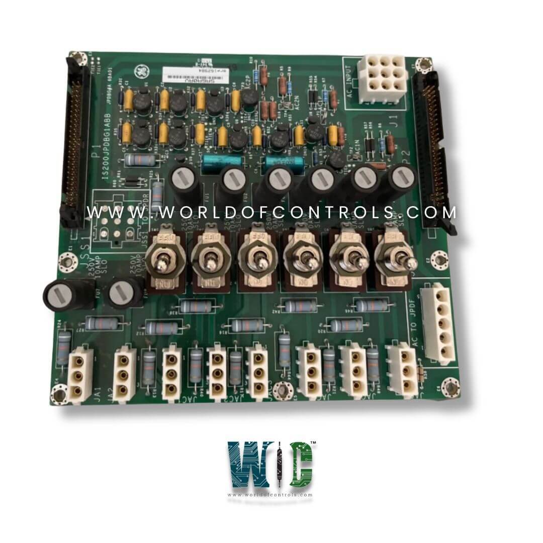
World Of Controls understands the criticality of your requirement and works towards reducing the lead time as much as possible.
IS200JPDBG1AAB - AC Power Distribution Module is available in stock which ships the same day.
IS200JPDBG1AAB - AC Power Distribution Module comes in UNUSED as well as REBUILT condition.
To avail our best deals for IS200JPDBG1AAB - AC Power Distribution Module, contact us and we will get back to you within 24 hours.
SPECIFICATIONS:
Part Number: IS200JPDBG1AAB
Manufacturer: General Electric
Series: Mark VIe
Product Type: AC Power Distribution Module
Number of Channels: 24
Number of inputs: 12
Board Rating: 115/230 V ac
Technology: Surface Mount
Total AC Circuit Loading: 10 A
Module Size: 26.41 cm High x 21.33 cm Wide
Mounting: Four Mounting Holes
Operating Temperature: 30 to 65°C
Repair: 3-7 Days
Availability: In Stock
Country of Origin: United States
Manual: GEH-6721D
FUNCTIONAL DESCRIPTION:
IS200JPDBG1AAB is an AC Power Distribution Module manufactured and designed by General Electric as part of the Mark VIe Series used in GE Distributed Turbine Control Systems. The AC Power Distribution (JPDB) board conditions, monitors, and distributes AC power. The module contains two line filters and an IS200JPDB circuit board. The module features two separate ac distribution circuits, each rated for 20 A at 115 or 230 V ac. The input circuits should be wired in parallel to avoid PPDA alarms when a single source of ac power is provided. For each circuit, one fused and three fused and switched branch circuit outputs are provided. Connection to an optional JPDF 125 V dc distribution module is provided.
The IS200JPDB includes passive monitoring circuits for both ac magnitudes as well as status feedback for all fused circuits. The monitoring circuits are on connector P1, compatible with cable connection to a board containing a power diagnostic PPDA I/O pack. IS200JPDB also has a P2 connector for pass-through of monitoring signals from other power distribution system cards. Two JPDB modules could be cabled into a single PPDA I/O pack when needed. IS2020JPDBG2 provides an additional connector when an ac source selector is required in a system.
The connector intercepts the two ac sources supplied to JPDB and routes them to the JSS1 connector on the board edge. The output of the ac selector is then wired to JSS1 and conducted to the individual branch circuit outputs.
INSTALLATION:
The IS200JPDB module is base-mounted vertically on a metal back base in a cabinet used by the PDM. A connection must be made between the IS2020JPDB sheet metal and the system Protective Earth. Input power is applied to terminals AC1H (line) and AC1N (neutral) for the first ac circuit and AC2H (line) and AC2N (neutral) for the second ac circuit. Both ac inputs are required to have grounded neutral connections. Output circuits are connected as documented for the system. If the power distribution system includes a PPDA power diagnostic I/O pack, a 50-pin ribbon cable is required from JPDB connector P1 to the P2 connector on the board holding the PPDA. It is permissible for this connection to pass through other core PDM boards using the P2 connector.
OPERATION:
Two sources of ac power are wired to a terminal board on the right side of the JPDB module. The ac power goes to the ac line filter assemblies underneath the IS200JPDB circuit board. A wire harness connects the filter assemblies to the JPDB circuit board J1 connector. The IS200JPDBG01 module uses the IS200JPDBG1A circuit board. This board does not provide a connection for an ac source selector, and J1 ac power is wired directly to the output branch circuits.
The board is designed for use with an ac source selector. It features the JSS1 connector mounted to the board. External filtered ac from connector J1 is fed to JSS1. The source selector output returns to the JSS1 to supply the branch circuit outputs. JAF1 feeds power directly from input connector J1 to an adjacent optional JPDF board to power two DACA power conversion modules. The DACA modules convert the ac power to 125 V dc to be used as an ac backup for systems using a 125 V dc battery.
WOC offers the largest stock of OEM Replacement Parts for GE Distributed Control Systems. We can also repair your faulty boards and supply unused and rebuilt boards backed up with a warranty. Our team of experts is available around the clock to support your OEM needs. Our team of experts at WOC is happy to assist you with any of your automation requirements. For pricing and availability on parts and repairs, kindly contact our team by phone or email.
What are the standard voltage and current ratings for AC Power Distribution Modules?
AC Power Distribution Modules are designed to handle various voltage and current ratings depending on the application. Common voltage ratings include 120V, 230V, and 400V AC, while current ratings can range from 10A to over 100A.
How does the JPDB module in GE turbine control systems handle AC power input?
The JPDB (Junction Power Distribution Board) module features two AC input screw terminal pairs on terminal strip TB1, each rated at 20A RMS. These terminals provide secure and efficient power input connections, ensuring stable power distribution within the turbine control system.
What is the maximum branch circuit protection for the JPDB module?
The JPDB module should have branch circuit protection that does not exceed a 30A circuit breaker rating. This ensures the system operates within safe current limits, preventing overheating and electrical damage. Using a breaker larger than 30A could pose safety risks by allowing excessive current to flow.